

Hydraulic power output unit and hydraulic hybrid drive system including same
- Summary
- Abstract
- Description
- Claims
- Application Information
AI Technical Summary
Benefits of technology
Problems solved by technology
Method used
Image

Examples
first embodiment
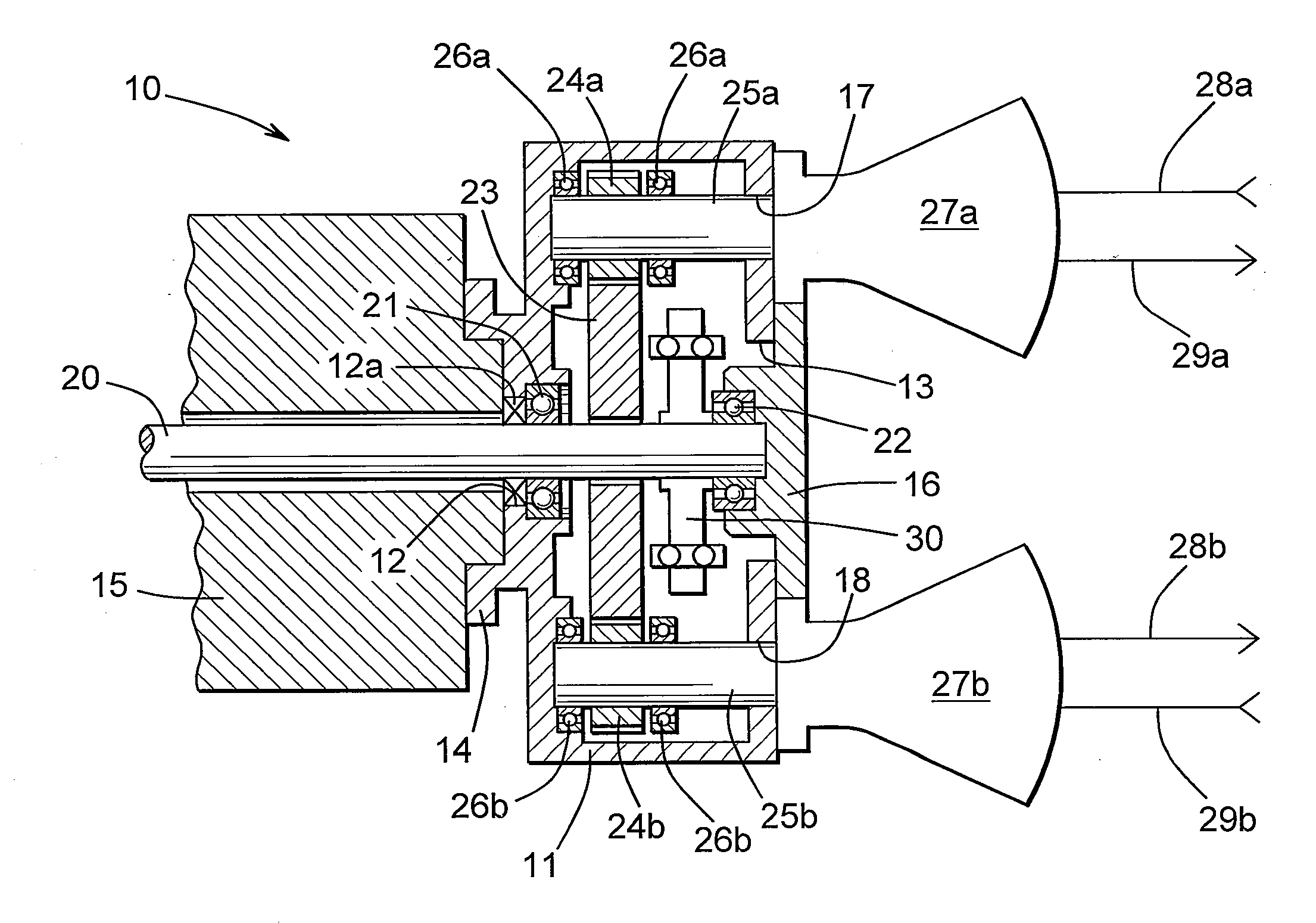
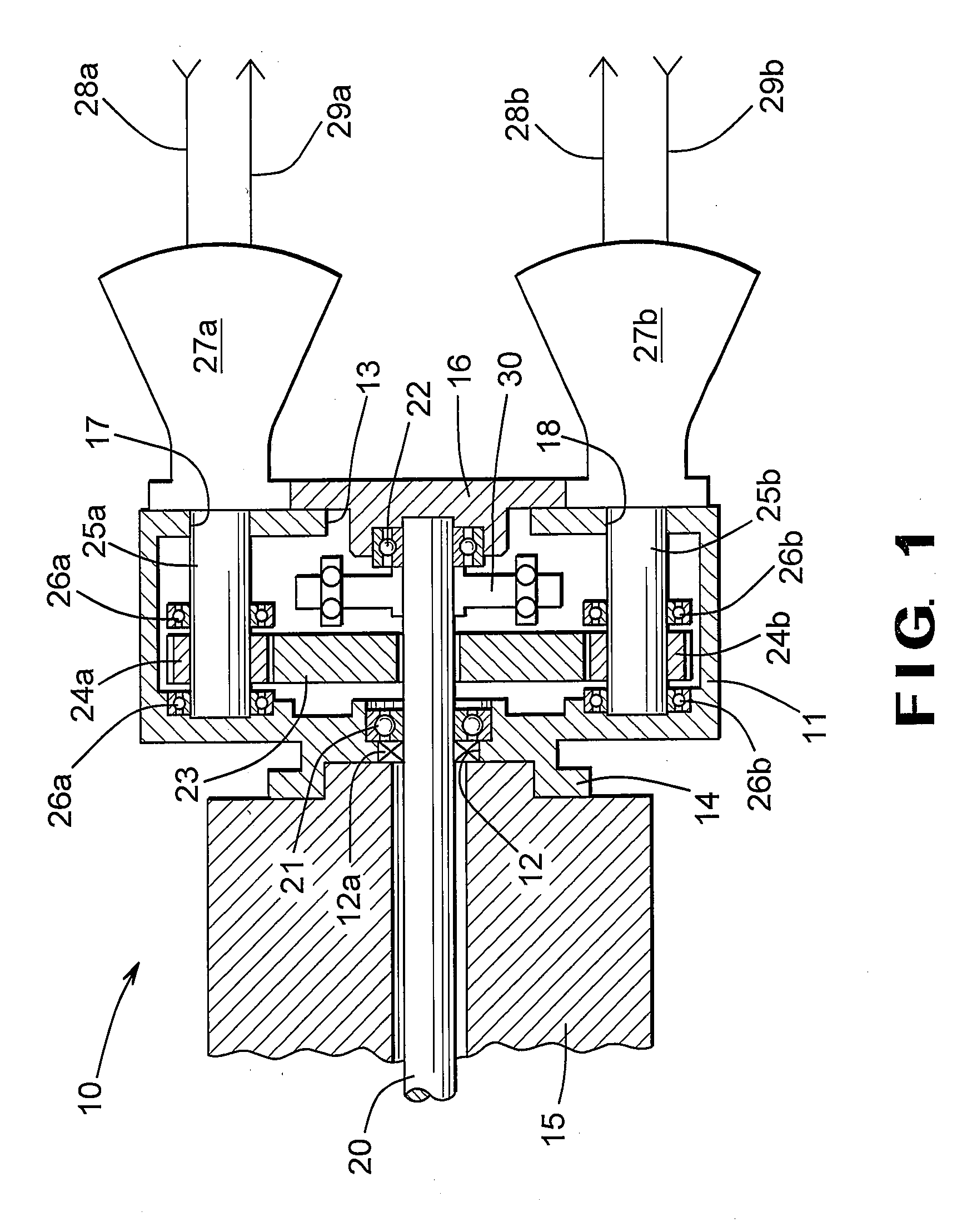
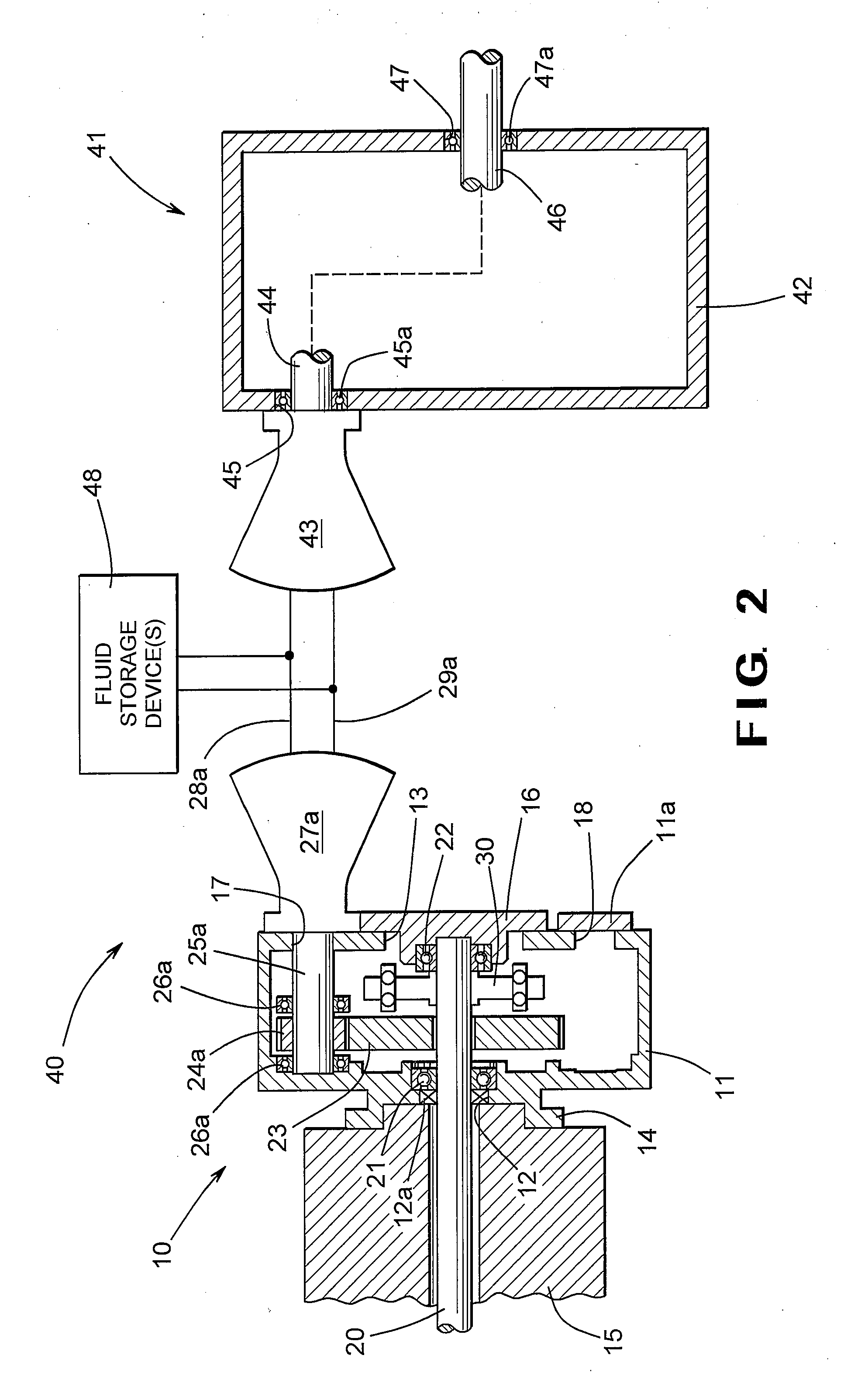
[0023]FIG. 2 is a schematic diagram of the hydraulic power output unit 10 illustrated in FIG. 1 used together with a hydraulic hybrid drive system, indicated generally at 40. The structure and manner of operation of the hydraulic power output unit 10 is substantially the same as described above with regard to FIG. 1, with the exception that in the embodiment illustrated in FIG. 2, the hydraulic power output unit 10 includes only a single one of the driven gears 24a, driveshafts 25a, bearing pairs 26a, and hydraulic pumps 27a. As described above, a cover 11 a covers the fourth opening 18 formed through in the second side of the housing 11.
[0024]The hydraulic hybrid drive train 40 also includes a drive unit, indicated generally at 41. The drive unit 41 is spaced apart from the hydraulic power output unit 10 and is preferably located between a pair of opposed side rails of the frame of the vehicle. The drive unit 41 is generally conventional in the art and includes a housing 42 having ...
second embodiment
[0029]FIG. 3 is a schematic diagram of the hydraulic power output unit 10 illustrated in FIG. 1 used together with a hydraulic hybrid drive system, indicated generally at 50. The structure and manner of operation of the hydraulic power output unit 10 is substantially the same as described above with regard to FIG. 1.
[0030]The hydraulic hybrid drive train 50 also includes a drive unit, indicated generally at 51. The drive unit 51 is spaced apart from the hydraulic power output unit 10 and is preferably located between a pair of opposed side rails of the frame of the vehicle. The drive unit 51 is generally conventional in the art and includes a housing 52 having opposed first and second sides. The drive unit 51 includes a hydraulic motor 53 that communicates through the lines 28a and 29a with the first hydraulic pump 27a of the hydraulic power output unit 10. By locating the hydraulic motor 53 on the first side of the housing 52 that is located nearest to the first hydraulic pump 27a ...
PUM
 Abstract
Description
Claims
Application Information