Integrated repeater

a repeater and integrated technology, applied in the field of repeaters, can solve the problems of limiting or precluding the placement of base station sites in the optimal locations, the repeater itself represents a significant percentage of the total hardware cost, and the hardware cost is only a portion of the total cost of the repeater si

Inactive Publication Date: 2005-08-23
COMMSCOPE TECH LLC
View PDF79 Cites 284 Cited by
  • Summary
  • Abstract
  • Description
  • Claims
  • Application Information

AI Technical Summary

Problems solved by technology

This conflicts with the pressure from investors and stockholders to increase earnings and decrease expenses.
In addition, local zoning and regulatory pressures often limit or preclude placement of base station sites in the optimum locations.
For a repeater site, the repeater itself represents a significant pe...

Method used


Image

  • Integrated repeater
  • Integrated repeater
  • Integrated repeater

Examples


Embodiment Construction

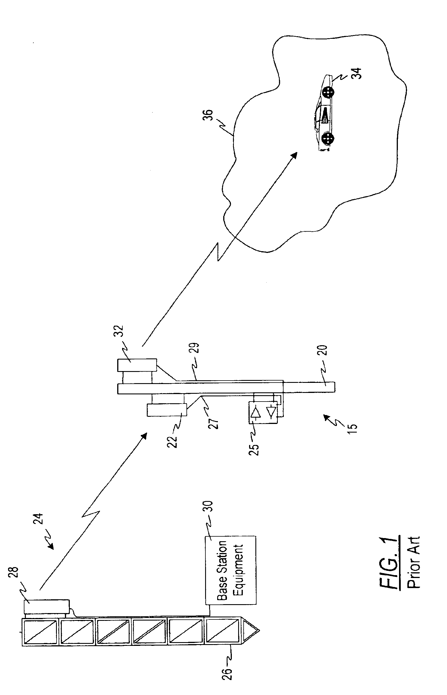
[0046]Referring initially to FIG. 1, a typical prior art repeater implementation 15 is illustrated. A repeater system resides on a mast or tower 20 and includes a donor antenna 22 for exchanging signals with a base station 24 at a remote location. The base station 24 may include a tower 26, transmit and receive antennas 28 and base station equipment 30.

[0047]Referring again to the repeater implementation 15, a second or null antenna 32 exchanges signals with the subscriber which may be a mobile subscriber as illustrated by an automobile at reference numeral 34. The null antenna 32 may be designed, located and installed so as to provide coverage over a null fill area 36, as will be described later herein.

[0048]The donor and null antennas 22, 32 are coupled with the repeater electronics 25 which is mounted elsewhere on the mast or tower 20 by runs of coaxial cable 27, 29.

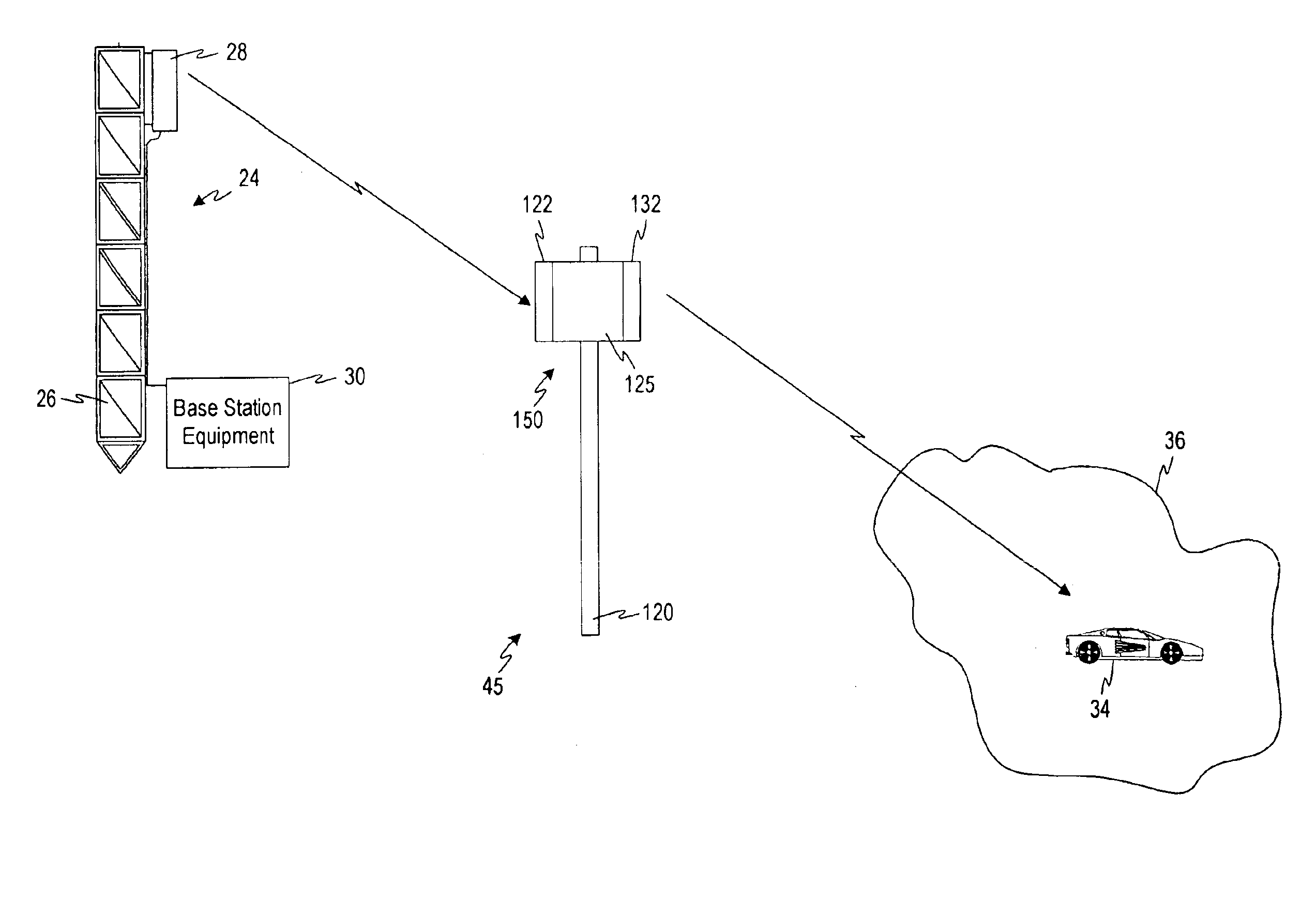
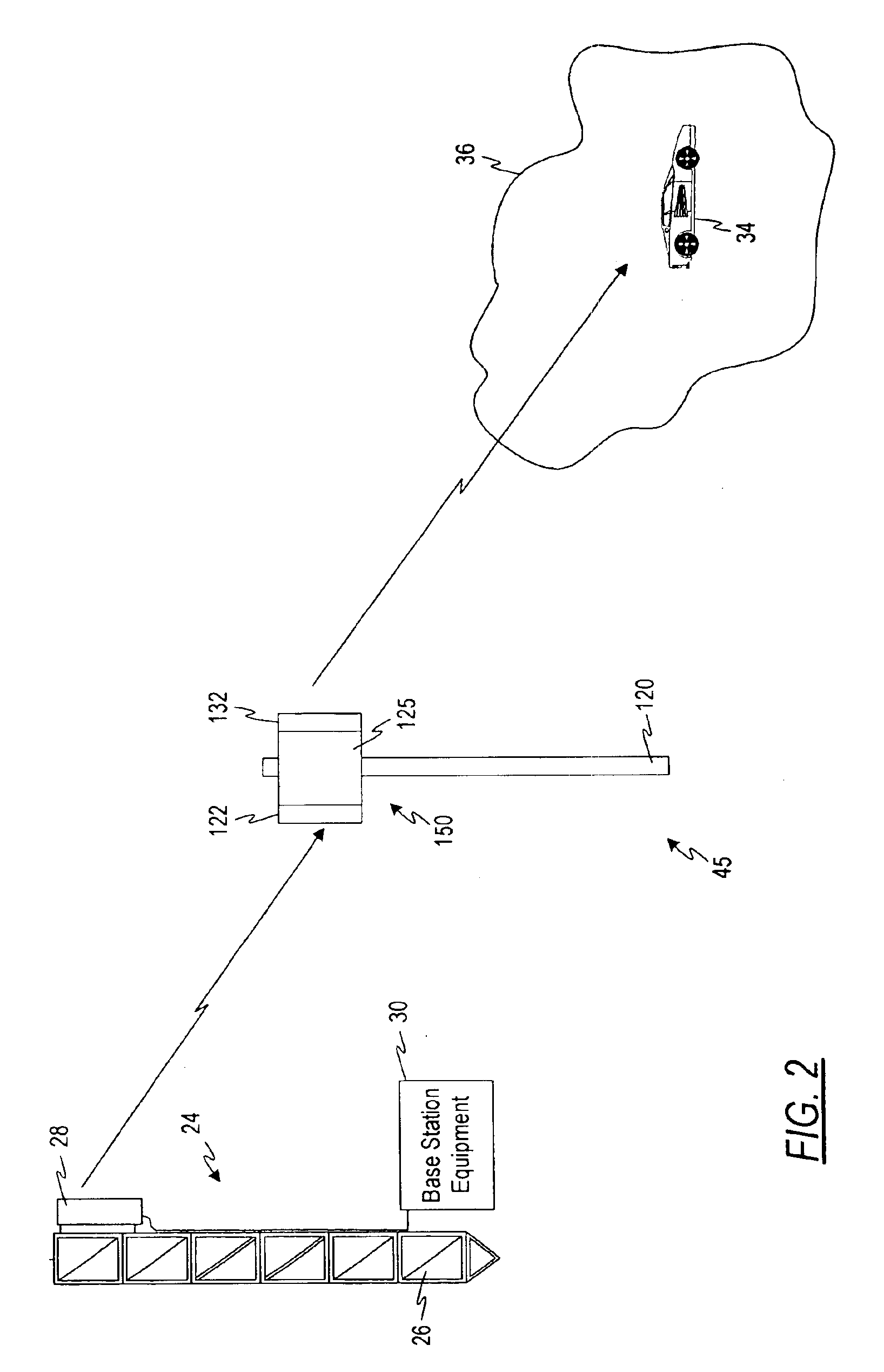
[0049]Referring now to FIG. 2, a repeater implementation in accordance with one embodiment of the invention is desi...


PUM


Abstract

An integrated repeater includes a housing having opposing sides, a donor antenna mounted on one of the opposing sides, a null antenna mounted on the other of the opposing sides, and repeater electronics mounted in the housing and operatively interconnecting the donor antenna and the null antenna. The repeater electronics include a beamforming arrangement for creating a desired antenna pattern of the donor antenna relative to a base station and a desired antenna pattern of the null antenna relative to subscriber equipment, and interference cancellation electronics for cancelling interference feedback signals between the donor antenna and the null antenna in both an uplink path and a downlink path.

Description

CROSS-REFERENCE TO RELATED APPLICATION[0001]This application is a continuation-in-part of the following prior U.S. patent applications: Ser. No. 09 / 357,032, filed Jul. 20, 1999 entitled “Side-to-Side Repeater”; Ser. No. 09 / 483,234, filed Jan. 14, 2000 entitled “Adaptive Cancellation for Wireless Repeaters” and Ser. No. 09 / 483,649, filed Jan. 14, 2000 entitled “RF Switched Beam Planar Antenna”. The disclosures of these applications are incorporated herein by reference.[0002]U.S. patent application Ser. No. 09 / 483,649 is a continuation-in-part of U.S. patent application Ser. No. 09 / 357,032, filed Jul. 20, 1999.FIELD OF THE INVENTION[0003]This invention is directed to a repeater which is more “user friendly” than any repeater on the market today, and, in addition, which offers a reduction in hardware, installation, and alignment costs for a repeater site.[0004]The invention is applicable to numerous markets where repeaters are used. Some of these applications include Cellular, PCS (Per...

Claims


Application Information

Patent Timeline
IPC IPC(8): H01Q1/00H01Q23/00H01Q3/26H01Q21/28H01Q21/29H01Q25/00H01Q21/00H04B7/155
CPCH01Q1/007H01Q3/2611H01Q3/2647H01Q21/28H01Q21/29H01Q23/00H01Q25/005H04B7/15585
Inventor LOVINGGOOD, BRECK W.JUDD, MANO D.KUIPER, WILLIAM P.
Owner COMMSCOPE TECH LLC
Why Eureka
Try Eureka