Fluidic mixer in microfluidic system

a microfluidic system and mixer technology, applied in the direction of flow mixers, fluid speed measurement, valve details, etc., can solve the problems of high tool-up costs, inability to quickly prototyping and manufacturing flexibility, and inability to meet the needs of fluid mixing in a microfluidic system

Inactive Publication Date: 2005-08-30
AGILENT TECH INC
View PDF70 Cites 82 Cited by
  • Summary
  • Abstract
  • Description
  • Claims
  • Application Information

AI Technical Summary

Problems solved by technology

In most instances, however, these techniques do not lend themselves to rapid prototyping and manufacturing flexibility.
Moreover, the tool-up costs for such techniques are often quite high and can be cost-prohibitive.
Generally, the mixing of fluids in a microfluidic system is problematic, since fluid flow within these devices is not turbulent.
Systems providing such utility are complicated and require electrical contacts and associated controls.
Additionally such systems only work with charged fluids, or fluids containing electrolytes.
Finally, these systems require voltages that are sufficiently high as to cause electrolysis of water, thus forming bubbles that complicate the collection of samples without destroying them.

Method used


Image

  • Fluidic mixer in microfluidic system
  • Fluidic mixer in microfluidic system
  • Fluidic mixer in microfluidic system

Examples


example devices

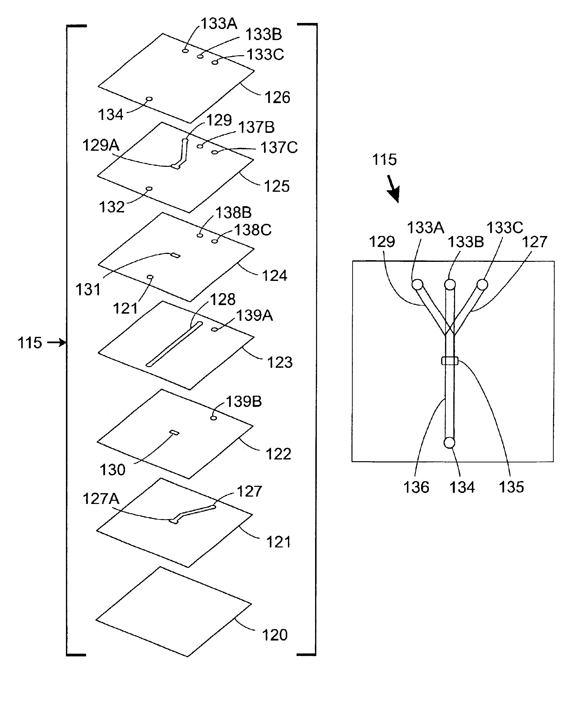
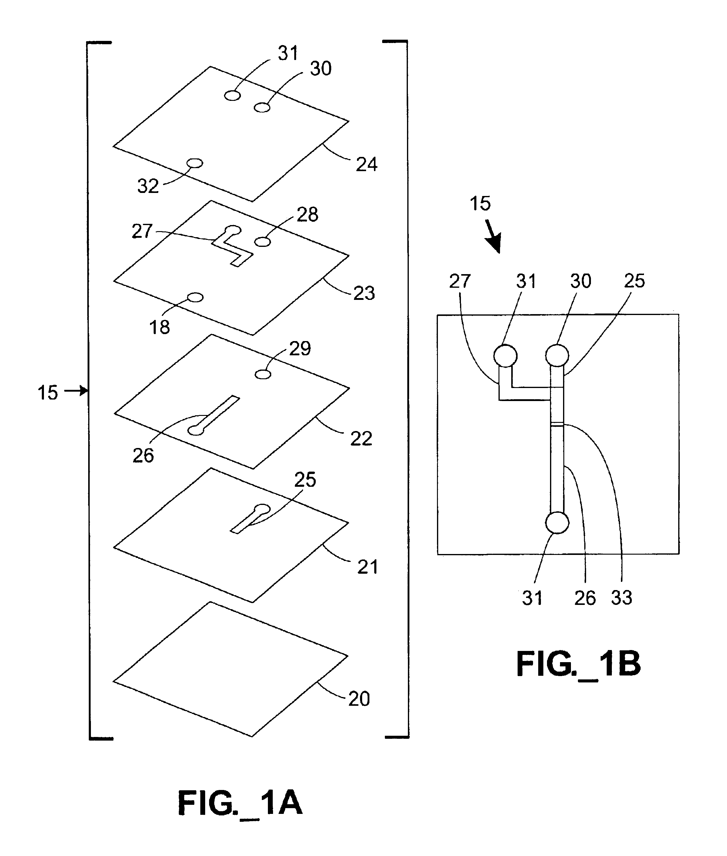
[0041]In the embodiment shown in FIGS. 1A-1B, a microfluidic mixing device 15 is constructed using sandwiched stencil sheets. Referring to FIG. 1A, a microfluidic mixing device 15 is constructed by stacking three stencil sheets 21-23 and sandwiching and adhering them between upper and lower substrates or cover sheets 20, 24. The stencil sheets 21-23 define various channels 25-27 and apertures or through-holes 18, 28, 29. Since the channels 25-27 are defined through the entire thickness of stencil sheets 21-23, respectively, the height of each channel 25-27 is equal to the thickness of its corresponding stencil sheet 21-23. Inlet ports 30, 31 and an outlet port 32 are defined in the upper cover sheet 24. The assembled device 15 is shown in FIG. 1B. In use, a first fluid is injected into a first inlet port 30, passes through through-holes 28, 29 in two sheets 23, 22 and enters an inlet channel 25. A second fluid enters a second inlet port 31 and passes through another inlet channel 27...


PUM

PropertyMeasurementUnit
widthaaaaaaaaaa
depthaaaaaaaaaa
depthaaaaaaaaaa

Abstract

Microfluidic devices capable of efficiently mixing two or more fluid are provided. Two or more microfluidic inlet channels defined in different sheets of material meet at an overlap region in fluid communication with an outlet channel. The channels are defined through the entire thickness of stencil sheets. The overlap region may include an aperture-defining spacer layer, and / or an impedance element, such as a porous membrane, adapted to distribute at least one fluid across the entire width of the outlet channel to promote reliable fluid mixing.

Description

STATEMENT OF RELATED APPLICATION(S)[0001]The present application is a continuation-in-part of U.S. patent application Ser. No. 09 / 632,681, filed Aug. 7, 2000 now abandoned.FIELD OF THE INVENTION[0002]The present invention relates to microfluidic devices and the mixing of fluids within those devices. Such devices are useful in, for example, various biological and chemical systems, as well as in combination with other liquid-distribution devices.BACKGROUND OF THE INVENTION[0003]There has been a growing interest in the manufacture and use of microfluidic systems for the acquisition of chemical and biological information. In particular, microfluidic systems allow complicated biochemical reactions to be carried out using very small volumes of liquid. These miniaturized systems improve the response time of reactions, minimize sample volume, and lower reagent cost.[0004]Traditionally, microfluidic systems have been constructed in a planar fashion using silicon fabrication techniques. Repre...

Claims


Application Information

Patent Timeline
Patent Type & Authority Patents(United States)
IPC IPC(8): B01D17/00B01L3/00B01F13/00B01F5/06B81B1/00G01N35/00
CPCB01D17/00B01F13/0059B01L3/5027B81B1/002B01F5/0604B01D17/0208B01D17/08Y10T428/24744B01L3/502707B01L2300/0816B01L2300/0864B01L2300/0867B01L2300/0874B01L2300/0887B01L2300/165B01L2400/0406B01L2400/0487B81B2201/051G01N2035/00237G01N2035/00544Y10T428/24562Y10T137/8122Y10T137/2191Y10T137/2224B01F25/422B01F33/30
Inventor KARP, CHRISTOPH D.O'CONNOR, STEPHEN D.PATEL, PAREN P.
Owner AGILENT TECH INC
Why Eureka
Try Eureka