Multiple spray devices for automotive and other applications

Active Publication Date: 2006-03-21
DLHBOWLES INC
View PDF26 Cites 66 Cited by
  • Summary
  • Abstract
  • Description
  • Claims
  • Application Information

AI Technical Summary

Benefits of technology

[0023]In another preferred embodiment, the present invention takes the form of a fluidic device. Its elements include: (1) the fluidic insert described above, (2) a housing having a cavity configured to receive the fluidic insert, with the cavity having surfaces adapted to mate with a portion of the outer surfaces of the

Problems solved by technology

This task of achieving uniform distribution of cleaning fluid has not been easy for a number of reasons, including the complexity and changing nature of such automotive surfaces.
Nozzles such as these all have potential problems with uniformity of the distribution of cleaning fluid since they all have sprays emitted from the nozzles that impinge on limited area of the glass and then depend on the wiper to spread the fluid.
In some cases, puddling of fluid can occur and result in wiper blade lifting.
In other instances, there may not be enough wetting of the surfaces before a wiper sweeps across the surface to complete the cleaning process.
However when such sprays are aimed higher to compensate for the spray depression occurring at high speeds, overspray over the sides may result.

Method used


Image

  • Multiple spray devices for automotive and other applications
  • Multiple spray devices for automotive and other applications
  • Multiple spray devices for automotive and other applications

Examples


Embodiment Construction

[0040]Before explaining at least one embodiment of the present invention in detail, it is to be understood that the invention is not limited in its application to the details of construction and to the arrangements of the components set forth in the following description or illustrated in the drawings. The invention is capable of other embodiments and of being practiced and carried out in various ways. Also, it is to be understood that the phraseology and terminology employed herein are for the purpose of description and should not be regarded as limiting.

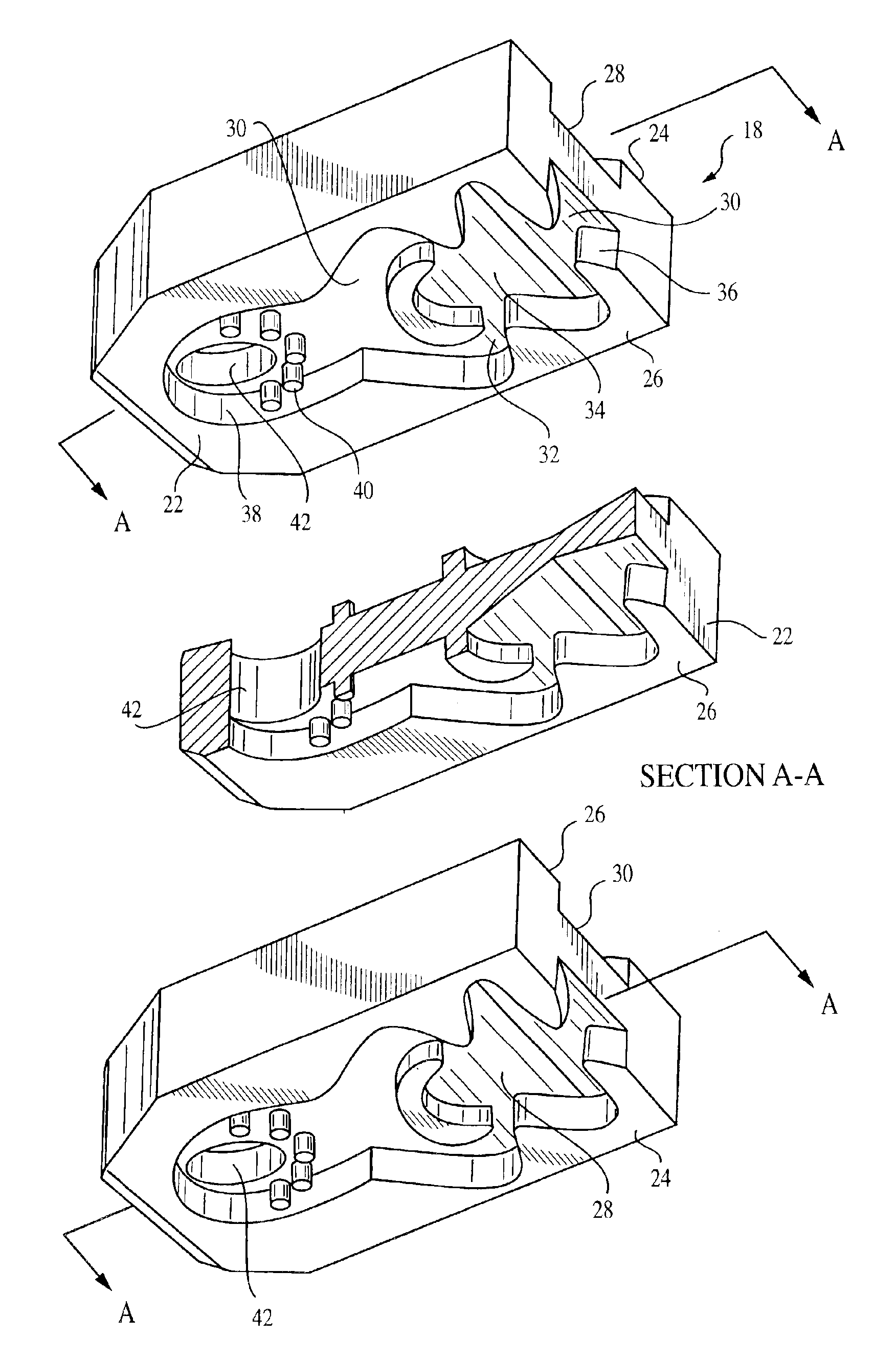
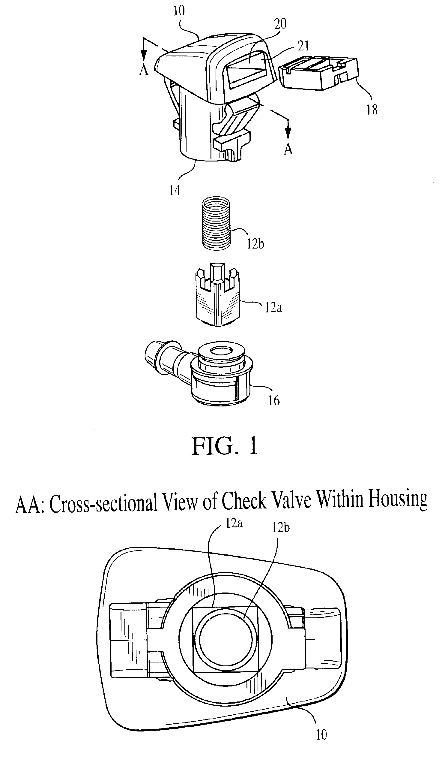
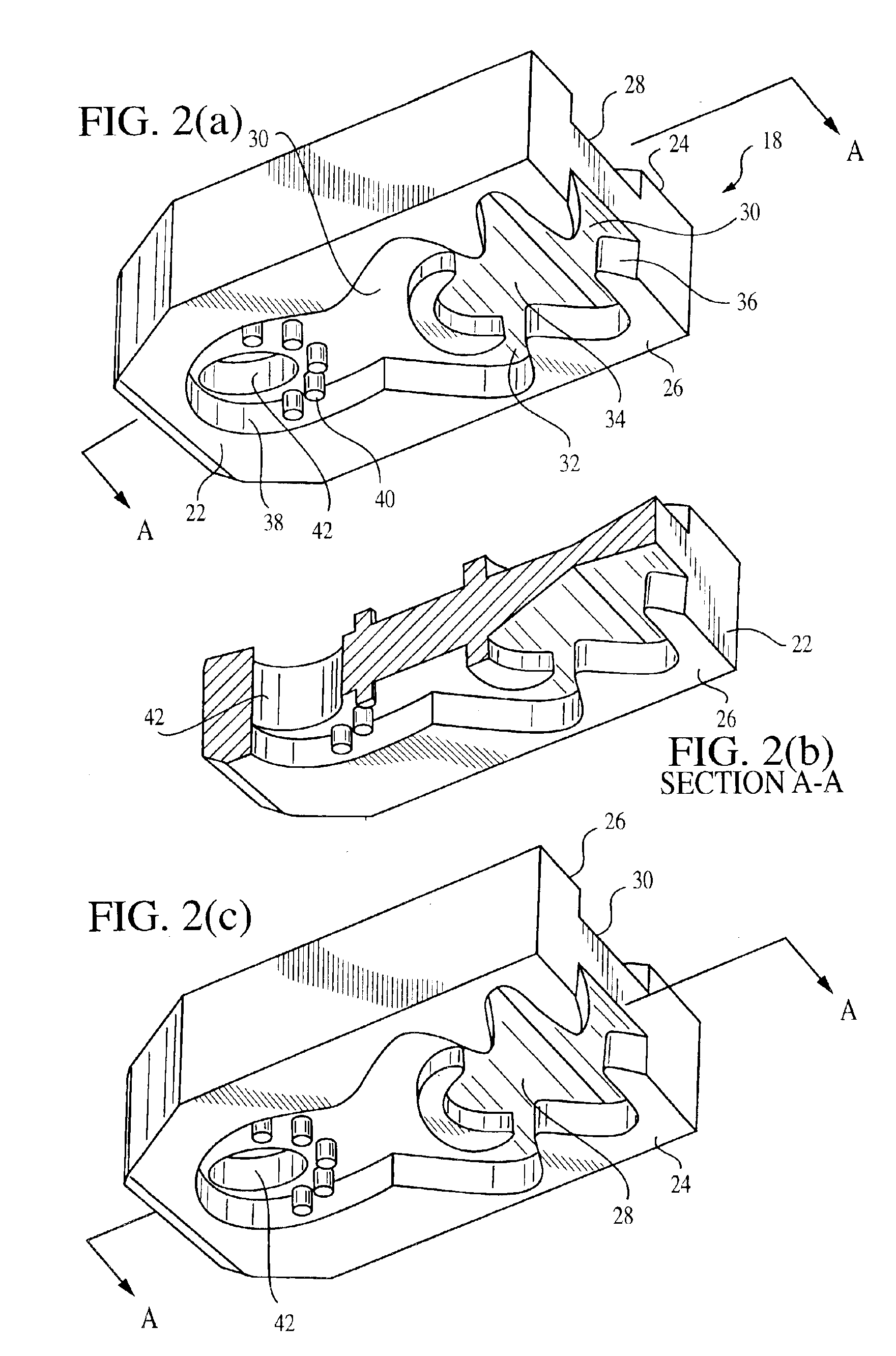
[0041]A preferred embodiment of the fluidic device of present invention is shown in FIG. 1. It is seen to consist of: (a) an automotive housing 10 of the type that is conventionally used to mount and align fluidic nozzles to clean windshields, (b) a check valve 12, consisting of a uniquely designed piston 12a and a spring 12b, which connects at the check valve's downstream end to the inlet of the housing flow tube 14, and at its up...


PUM


Abstract

A fluidic insert that receives fluid under pressure from a fluid inlet tube and generates a specified spatial distribution of the fluid exiting the insert includes: (1) a body member having top, bottom, front and rear outer surfaces, (2) top and bottom fluidic circuits located, respectively, at least partially within the member's top and bottom surfaces, wherein each of these circuits has at least one power nozzle, an interaction chamber, and an outlet whose exit lies within the member front surface, (3) the bottom fluidic circuit having a portion of its surface area located upstream of the power nozzle and adapted so that it can mate with a fluid inlet tube that supplies fluid to the insert, and (4) an inter-circuit flow passage that allows fluid to flow from the bottom fluid circuit to the top fluid circuit, the bottom end of this passage located such that it is downstream of the point where the inlet tube mates with the bottom circuit and upstream of the bottom circuit's power nozzle, with the top end of this passage located upstream of the top circuit's power nozzle.

Description

CROSS-REFERENCE TO RELATED APPLICATION[0001]This application claims the benefit of Provisional Patent Application No. 60 / 390,294, filed Jun. 20, 2002 by Keith Berning, Dan Steerman, Srinivasaiah Sridhara and Eric W. Koehler. The teachings of this application are incorporated herein by reference to the extent that they do not conflict with the teaching herein.BACKGROUND OF THE INVENTION[0002]1. Field of the Invention[0003]This invention relates to fluid handling processes and apparatus. More particularly, this invention relates to a fluid flow device that is suitable for use in liquid-gas applications such as the distribution of cleaning fluids to wash automotive windshield, headlamp and rear windshield surfaces.[0004]2. Description of the Related Art[0005]Automotive windshield, headlamp and rear windshield cleaning applications need an optimum distribution of cleaning fluid spread over the critical areas to be cleaned in order for adequate cleaning to be accomplished, with or withou...

Claims


Application Information

Patent Timeline
IPC IPC(8): B05B1/08B05B1/10B05B15/00B60S1/52F15C1/22
CPCB05B1/08F15C1/22B60S1/52B05B15/008B05B15/40Y10T137/0396Y10T137/2098Y10T137/2093
Inventor BERNING, KEITHSTEERMAN, DANIEL E.SRIDHARA, SRINIVASAIAHRUSSELL, GREGORY
Owner DLHBOWLES INC
Why Eureka
Try Eureka