Microfluidic free interface diffusion techniques

a microfluidic and free interface technology, applied in flow mixers, apparatuses with spatial temperature gradients, chemical vapor deposition coatings, etc., can solve the problems of unsuitable high-throughput screening applications of conventional macroscopic free interfaces, poorly defined fluidic interfaces, and widely used in crystallographic communities, etc., to achieve the effect of suppressing convective flow

Inactive Publication Date: 2008-07-31
CALIFORNIA INST OF TECH +1
View PDF65 Cites 63 Cited by
  • Summary
  • Abstract
  • Description
  • Claims
  • Application Information

AI Technical Summary

Benefits of technology

[0018]An embodiment of a method of reducing a concentration of a small molecule in a protein sample in accordance with the present invention comprises disposing a first static fluid containing the protein sample in a microfluidic channel, disposing a second static fluid having a low concentration of the small molecule proximate to the first fluid to form a fluidic interface, and suppressing convective flow of the first and second fluids such that the small molecule from the first static fluid diffuses across the interface solely by diffusion to reduce the concentration of small molecule present in the first static fluid.

Problems solved by technology

However, certain technical difficulties have rendered conventional macroscopic free interfaces unsuitable for high throughput screening applications, and they are not currently widely used in the crystallographic community for several reasons.
Unfortunately, the fluids may not be sucked into a capillary serially to eliminate this problem. FIGS. 31A-B show the mixing, between a first solution 9400 and a second solution 9402 in a capillary tube 9404 that would result due to the parabolic velocity distribution of pressure driven convective Poiseuille flow, also resulting in a poorly defined fluidic interface 9406.
For this reason cumbersome protocols are often used to define a macroscopic free-interface.
The problems of convective mixing associated with macroscopic free interface diffusion studies is compounded in that two fluids of differing density will mix by gravity induced convection if they are not stored at the proper orientation, additionally complicating the storage of reactions.
While the diffusion described by Kamholz et al. may be useful, it offers the distinct disadvantage of necessarily creating an elongated interface between the fluids, such that substantial volumes of the fluids are continuously exposed to the steep concentration gradient occurring at the interface between them.
In the context of a protein crystallization experimental protocol, one such disadvantage is the possibility of solvent shock and the precipitation of sample in non-crystalline form along the interface.

Method used


Image

  • Microfluidic free interface diffusion techniques
  • Microfluidic free interface diffusion techniques
  • Microfluidic free interface diffusion techniques

Examples


Embodiment Construction

[0098]Portions of the prior discussion have referenced the use of microfluidic structures to accomplish free interface diffusion in accordance with embodiments of the present invention. The following discussion relates to formation of microfabricated fluidic devices utilizing elastomer materials, as described generally in U.S. patent application Ser. No. 09 / 826,585 filed Apr. 6, 2001, 09 / 724,784 filed Nov. 28, 2000, and 09 / 605,520, filed Jun. 27, 2000. These patent applications are hereby incorporated by reference.

I. Microfabricated Elastomer Structures

[0099]1. Methods of Fabricating

[0100]Exemplary methods of fabricating the present invention are provided herein. It is to be understood that the present invention is not limited to fabrication by one or the other of these methods. Rather, other suitable methods of fabricating the present microstructures, including modifying the present methods, are also contemplated.

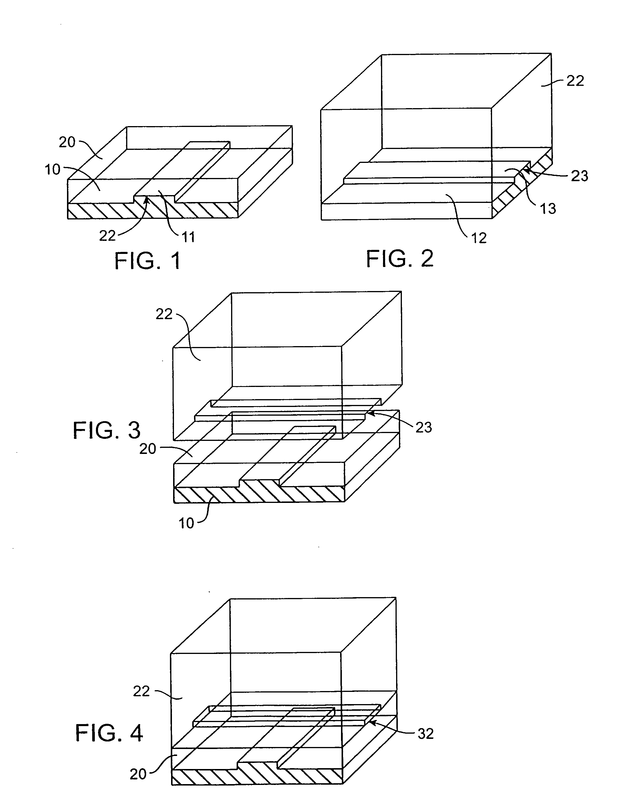
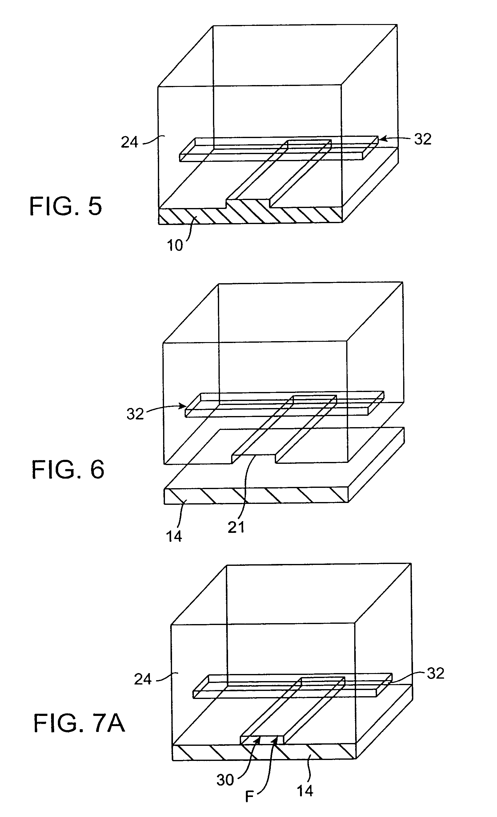
[0101]FIGS. 1 to 7B illustrate sequential steps of a first preferred ...


PUM

PropertyMeasurementUnit
widthaaaaaaaaaa
volumesaaaaaaaaaa
widthsaaaaaaaaaa

Abstract

A static fluid and a second fluid are placed into contact along a microfluidic free interface and allowed to mix by diffusion without convective flow across the interface. In accordance with one embodiment of the present invention, the fluids are static and initially positioned on either side of a closed valve structure in a microfluidic channel having a width that is tightly constrained in at least one dimension. The valve is then opened, and no-slip layers at the sides of the microfluidic channel suppress convective mixing between the two fluids along the resulting interface. Applications for microfluidic free interfaces in accordance with embodiments of the present invention include, but are not limited to, protein crystallization studies, protein solubility studies, determination of properties of fluidics systems, and a variety of biological assays such as diffusive immunoassays, substrate turnover assays, and competitive binding assays.

Description

CROSS-REFERENCES TO RELATED APPLICATIONS[0001]This application is a divisional of U.S. patent application Ser. No. 10 / 265,473, entitled “MICROFLUIDIC FREE INTERFACE DIFFUSION TECHNIQUES,” filed Oct. 4, 2002 (the “parent application”). The parent application is a Continuation-in-Part of U.S. patent application Ser. No. 09 / 826,583, filed Apr. 6, 2001, and is a Continuation-in-Part of 09 / 887,997, filed Jun. 22, 2001, and is a Continuation-in-Part of Ser. No. 10 / 117,978, filed Apr. 5, 2002. These prior patent applications are hereby incorporated by reference for all purposes.STATEMENT AS TO RIGHTS TO INVENTIONS MADE UNDER FEDERALLY SPONSORED RESEARCH OR DEVELOPMENT[0002]Work described herein has been supported, in part, by National Institute of Health grant HG-01642-02. The United States Government may therefore have certain rights in the invention.BACKGROUND OF THE INVENTION[0003]Free-interface diffusion techniques have been employed in a number of scientific applications, most notably...

Claims


Application Information

Patent Timeline
Patent Type & Authority Applications(United States)
IPC IPC(8): G01N33/53G01N33/536B01L3/00B01L7/00B01L9/00B81B3/00B81C1/00F04B43/04F15C5/00F16K99/00
CPCB01J2219/00355Y10T436/25B01J2219/00396B01J2219/00398B01J2219/00439B01J2219/005B01J2219/00527B01J2219/00605B01J2219/0061B01J2219/00612B01J2219/00619B01J2219/00621B01J2219/00635B01J2219/00637B01J2219/00659B01J2219/00707B01J2219/00722B01J2219/00725B01L3/502738B01L3/502746B01L3/502769B01L7/54B01L9/527B01L2200/025B01L2200/027B01L2200/0605B01L2200/10B01L2300/0681B01L2300/0861B01L2300/123B01L2300/14B01L2300/18B01L2400/0481B01L2400/0655B01L2400/0688B81B2201/051B81B2201/054B81B2201/058B81C1/00119B81C2201/034F04B43/043F16K99/0001F16K99/0015F16K99/0017F16K99/0059F16K2099/0074F16K2099/0078F16K2099/008F16K2099/0084F16K2099/0086B01F5/00B81B1/00B01F13/0093Y10T117/1012Y10T117/1004Y10T117/1008B01J2219/00378Y10T137/0324Y10T137/0318Y10T137/2224F04B43/14B01F33/3039C30B7/14C30B29/02B01F25/00
Inventor HANSEN, CARL L.QUAKE, STEPHEN R.BERGER, JAMES M.
Owner CALIFORNIA INST OF TECH
Why Eureka
Try Eureka