Method and device for adjusting bearing assembly for a wheel hub

a technology for bearing assemblies and hubs, which is applied in the direction of mechanical equipment, rigid support of bearing units, transportation and packaging, etc., can solve the problems of spacers further deformation

Inactive Publication Date: 2005-08-30
MERITOR LIGHT VEHICLE TECH LLC
View PDF3 Cites 20 Cited by
  • Summary
  • Abstract
  • Description
  • Claims
  • Application Information

AI Technical Summary

Benefits of technology

[0008]The subject invention provides a means of accurately and repeatedly setting the distance between bearing assemblies for a wheel hub assembly. Preferably the invention is used for wheel hub assemblies installed on heavy vehicles such as trucks and trailers pulled by such trucks. The invention includes a spacer assembled over the spindle and between the inner and outer bearing assemblies. The spacer may either be of a predetermined length machined to precise tolerances or a deformable spacer deformed under a load. The spacer with the predetermined machined length is machined to the precise length required for each specific application and configuration. The deformable spacer includes a first section having a wall thickness sized to deform a predetermined amount under a predetermined load. The amount of deformation changes an overall length of the spacer to set the distance between bearing assemblies. The spacers along with the bearing assemblies are then assembled to a spindle of the vehicle.
[0009]The spacer of this invention also includes at least one opening to provide for the free flow of lubricant through the spacer. The assembled spacer forms a leak resistance seal between the bearing assemblies that initially prevents oil from filling a cavity created about a wheel spindle. The opening position within the spacer allows lubricant to fill the cavity and thereby properly fill the wheel hub with lubricant. Further, the opening provides for the free flow of oil into and out of the cavity such that the bearings are supplied with the proper amount of lubricant during operation. The openings can be of any configuration including circular holes, slots and notches at the ends of the spacer. The only limitation being that the any opening must not weaken the spacer such that the spacer further deforms from pressure exerted by the nut.

Problems solved by technology

The only limitation being that the any opening must not weaken the spacer such that the spacer further deforms from pressure exerted by the nut.

Method used


Image

  • Method and device for adjusting bearing assembly for a wheel hub
  • Method and device for adjusting bearing assembly for a wheel hub
  • Method and device for adjusting bearing assembly for a wheel hub

Examples


Embodiment Construction

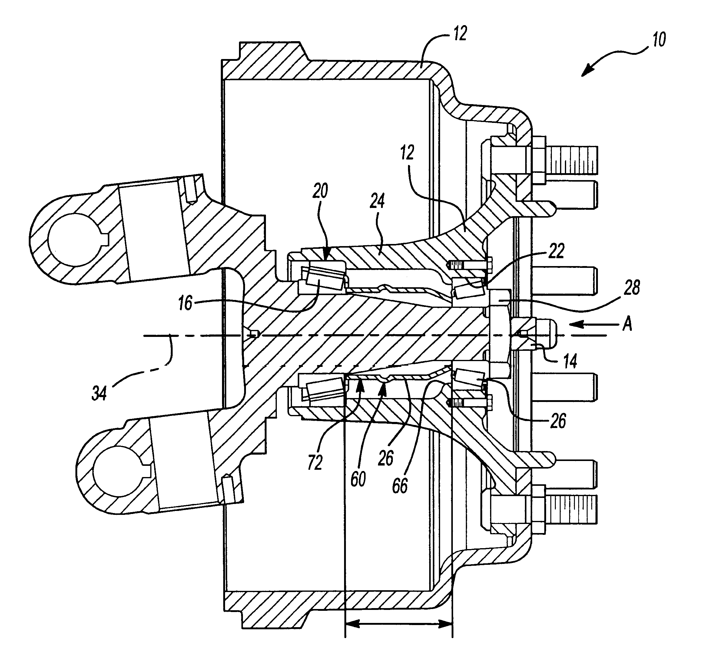
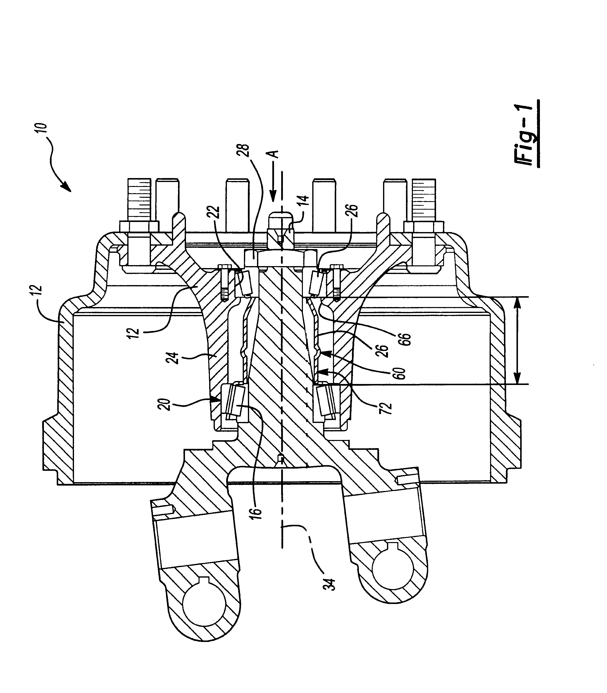
[0017]Referring to the Figures, wherein like numerals indicate like or corresponding parts throughout the several views, the subject invention is a wheel hub assembly generally shown at 10 in FIG. 1. The wheel hub assembly 10 includes a wheel hub 12 rotatably supported on a spindle 14 by inner and outer bearing assemblies 16,18. The bearing assemblies 16,18 include inner and outer bearing cones 15, 17 installed onto the spindle to engage inner and outer bearing cups 20,22 pressed into a central portion 24 of the wheel hub 12. A spacer 26 is in load bearing contact between the inner and outer bearing assemblies 16,18. Internal threads of a nut 28 engage external threads of the spindle 14 to secure the wheel hub assembly 12 to the spindle 14. The tightened nut exerts an axial force, indicated by arrow A along an axis 34 through the outer bearing assembly 18, the spacer 26, the inner bearing assembly 16 and finally to the spindle 14. The spacer 26 limits a length 32 between the inner a...


PUM


Abstract

A wheel hub assembly including first and second bearing assemblies positioned on opposite sides of a spacer. The spacer includes at least one opening to allow lubricant to flow through the spacer. The spacer includes a first section deformable such that an overall length of the spacer is reduced a predetermined amount in response to the application of a predetermined load to set a distance between the first and second bearing assemblies. The assembly further includes a spindle having external threads and a nut having internal threads engaged with the spindle to secure the bearing assemblies and spacer within the wheel hub assembly.

Description

[0001]This application claims priority to provisional application serial No. 60 / 299,689 filed on Jun. 20, 2001 and provisional application Ser. No. 60 / 301,565 filed on Jun. 28, 2001.BACKGROUND OF THE INVENTION[0002]This invention relates to a method and device for adjusting the distance between inner and outer bearing assemblies of a wheel hub to assure proper and consistent alignment.[0003]Typically, a wheel assembly will include inner and outer bearing assemblies to support rotation of a wheel hub about a spindle. A nut threaded onto corresponding threads of the spindle secures the wheel hub between bearing assemblies such that the wheel hub freely rotates on the bearing assemblies. The nut is fastened with sufficient torque to apply a predetermined amount of pressure to the bearing assemblies in order to properly support the wheel hub. Insufficient torque can cause misalignment of the wheel hub and premature wear on the bearing assemblies and excessive torque can cause excessive ...

Claims


Application Information

Patent Timeline
Patent Type & Authority Patents(United States)
IPC IPC(8): F16C35/04F16C35/06F16C33/66F16C19/54F16C43/04
CPCF16C19/548F16C33/6651F16C35/061F16C43/04F16C2326/02F16C19/364F16C25/06
Inventor STANCZAK, EDMUND A.
Owner MERITOR LIGHT VEHICLE TECH LLC
Why Eureka
Try Eureka