Tape head with thin support surface and method of manufacture

a technology of support surface and tape head, which is applied in the direction of manufacturing head surface, maintaining head carrier alignment, instruments, etc., can solve the problems of signal loss, excessive tape damage, increased media speed,

Active Publication Date: 2005-08-30
QUANTUM CORP
View PDF70 Cites 42 Cited by
  • Summary
  • Abstract
  • Description
  • Claims
  • Application Information

AI Technical Summary

Benefits of technology

[0012]In another aspect, an exemplary magnetic head assembly for writing and / or reading from a magnetic recording media is described. The head assembly may include a major support surface for contacting and supporting the media; the major support surface including a width measured along a direction the media is advanced. One or more active device regions may be positioned within the major support surface and may include sets of read and / or write transducers. The head assembly further includes a thin support surface having a width measured along the direction the media is advanced. The major support surface and thin support surface are at least partially separated by a slot extending transversely to the direction the media is advanced and the width of the thin support surface is selected to effect a predetermined wear of the thin support surface.

Problems solved by technology

During the recording or reproducing process, the small separation reduces the coupling between the tape field and the reproducing element, causing a signal loss.
Increased media speed, however, may entrap air between a support surface of the tape head and the tape.
The air may cause increased separation between the magnetic tape and the support surface leading to signal loss and / or excessive tape damage.
If the wrap angle is too large, a bubble or arc may occur, creating a separation between the tape and the head structure.
Further, if the wrap angle is too small the tape may entrap air as it advances over the head structure and increases the separation therebetween.
Manufacturing contoured tape heads with desired wrap angles is generally costly and complicated.
Additionally, increased tension and pressure to prevent spacing has several deleterious consequences.
For example, increased tension and pressure may reduce tape life and increase the possibility of tape damage and data loss.
Tape damage may lead to increased lateral tape motion and decreased reliability.
Also, increased tension and pressure may cause the head structure to wear down more quickly resulting in shortened head life.

Method used


Image

  • Tape head with thin support surface and method of manufacture
  • Tape head with thin support surface and method of manufacture
  • Tape head with thin support surface and method of manufacture

Examples


Embodiment Construction

[0019]The following description is presented to enable any person skilled in the art to make and use the invention. Descriptions of specific materials, techniques, and applications are provided only as examples. Various modifications to the examples described herein will be readily apparent to those skilled in the art, and the general principles defined herein may be applied to other examples and applications without departing from the spirit and scope of the invention. Thus, the present invention is not intended to be limited to the examples described and shown, but is to be accorded the scope consistent with the appended claims.

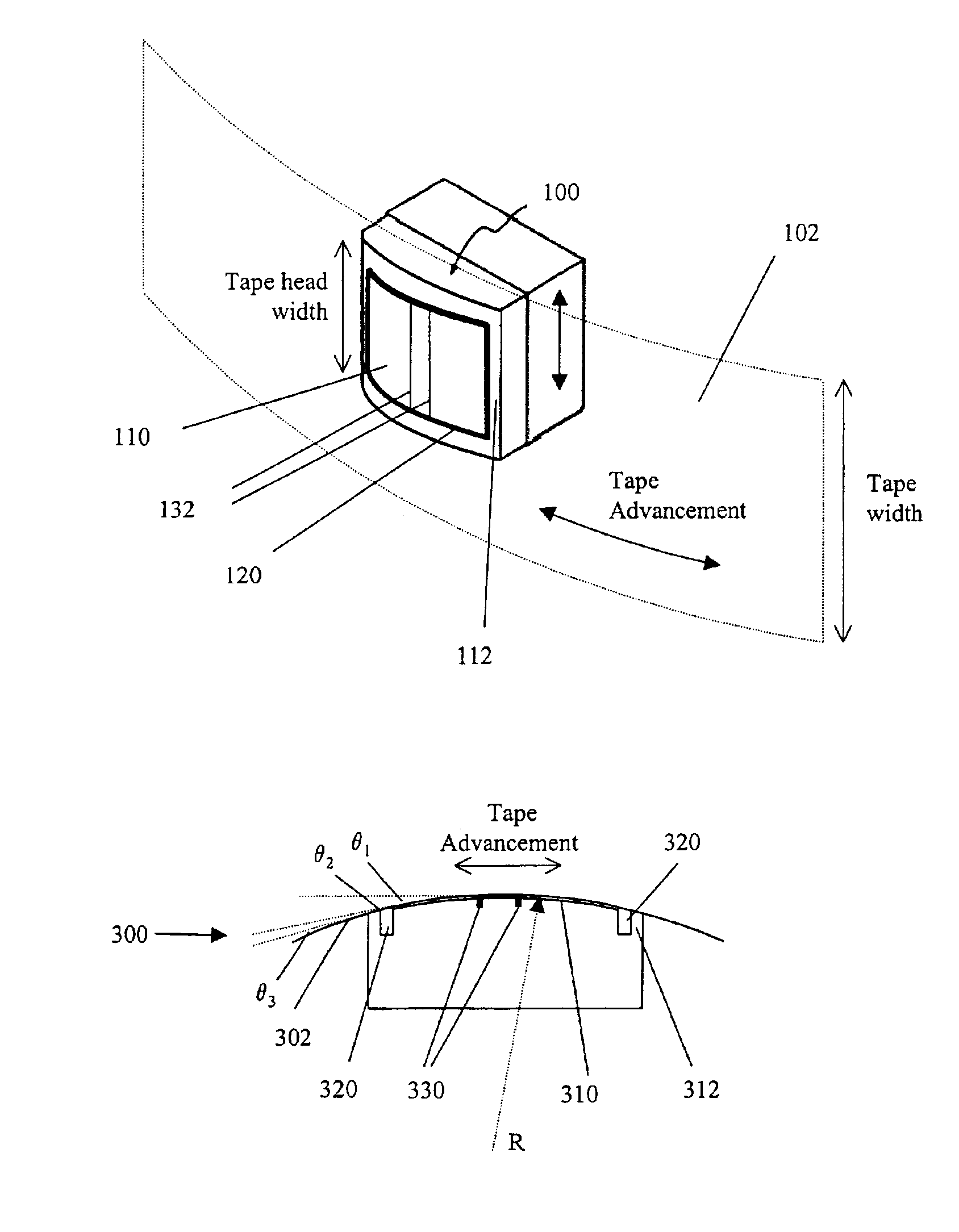
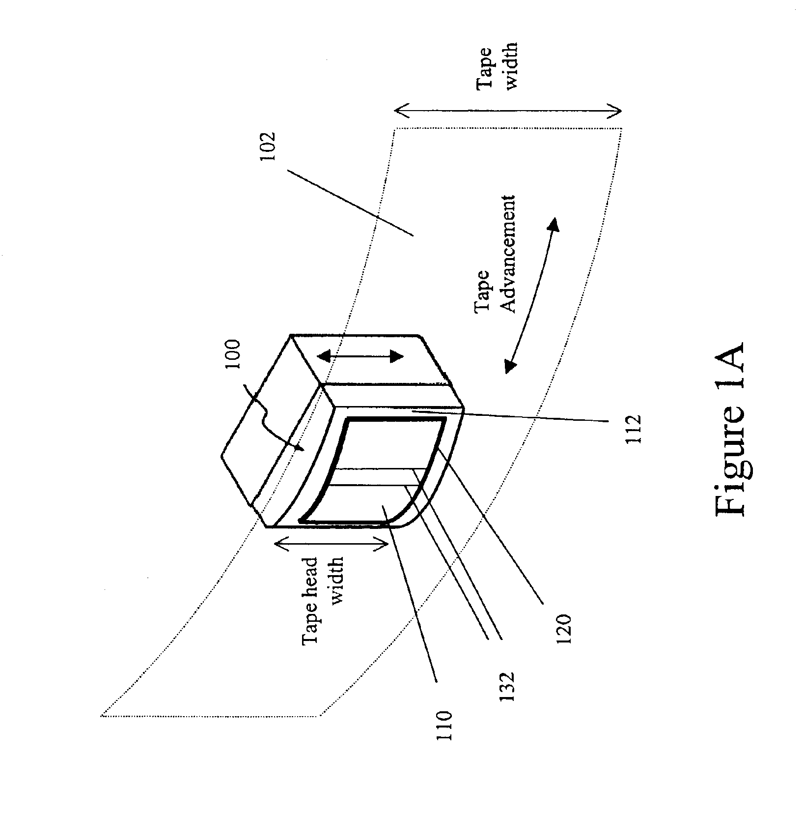
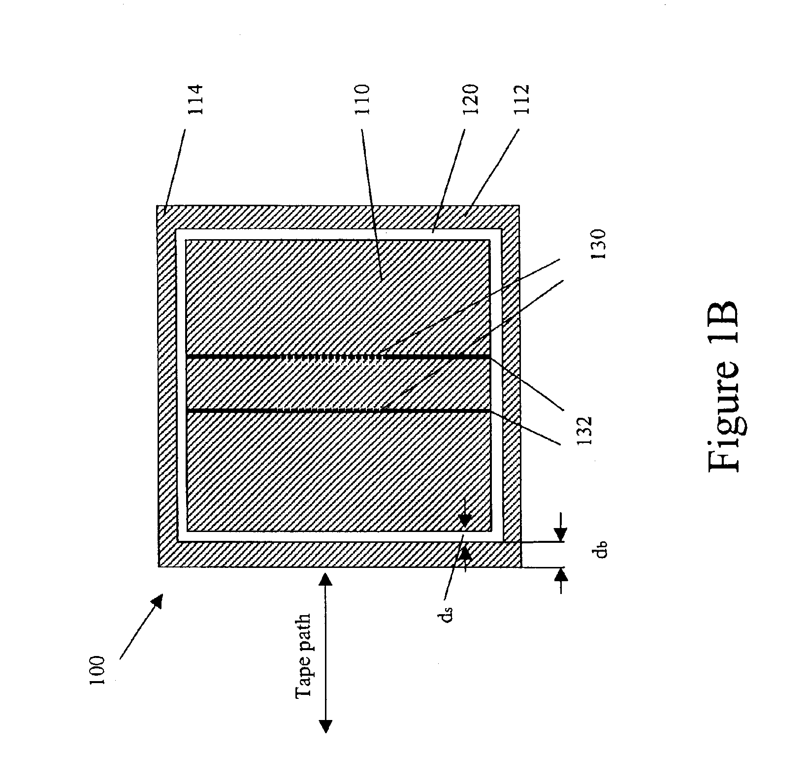
[0020]In one aspect, an exemplary magnetic head assembly may provide enhanced airflow control and reduced tape damage by controlling the wrap angle between the magnetic tape and the magnetic head structure. The exemplary magnetic head design includes a slot formed near the leading and / or trailing edge of the head structure creating a relatively thin support...


PUM

PropertyMeasurementUnit
speedsaaaaaaaaaa
wrap anglesaaaaaaaaaa

Abstract

According to one aspect, an exemplary method of manufacturing a magnetic head assembly with a predetermined wrap angle is described. The method includes removing a portion of a magnetic head support surface to create a slot transverse to a direction the media advances and at least partially separating a major support surface having an active device region and a thin support surface. The method further includes removing a portion of the thin support surface such that the height of at least a portion of the thin support surface is reduced relative to the major support surface. The height may be reduced to achieve a predetermined wrap angle between the media and the major support surface of the head assembly.

Description

BACKGROUND OF THE INVENTION[0001]1. Field of the Invention[0002]The present invention relates generally to magnetic tape read and / or write heads, and more particularly to magnetic tape read and / or write heads with a slot formed on a supporting surface of the head.[0003]2. Description of the Related Art[0004]Magnetic tape continues to be an efficient and effective medium for data storage in computer systems. Increased data storage capacity and retrieval performance is desired of all commercially viable mass storage devices and media. In the case of linear tape recording, a popular trend is toward multi head, multi-channel fixed head structures with narrowed recording gaps and data track widths so that many linear data tracks may be achieved on a tape medium of a predetermined width, such as one-half inch width tape. To increase the storage density and reduce access time of magnetic tapes, data tracks on the tape are arranged with greater density and the tape is streamed by a tape hea...

Claims


Application Information

Patent Timeline
Patent Type & Authority Patents(United States)
IPC IPC(8): G11B5/187G11B5/10G11B5/255G11B15/62G11B5/31
CPCG11B5/102G11B5/1871Y10T29/49041G11B5/3106G11B15/62G11B5/255
Inventor SALIBA, GEORGE
Owner QUANTUM CORP
Why Eureka
Try Eureka