Electrical assembly including an electrical tie

a technology of electrical assemblies and electrical ties, which is applied in the direction of hose connections, flexible elements, packaging, etc., can solve the problems of electrical ties that cannot be rigidly mounted to a separate mounting structure, and the scope of applications of electrical ties is quite limited

Inactive Publication Date: 2005-09-06
GROUP DEKKO
View PDF28 Cites 29 Cited by
  • Summary
  • Abstract
  • Description
  • Claims
  • Application Information

AI Technical Summary

Benefits of technology

[0011]An advantage of the present invention is that the longitudinally extending ribs on the elongate strap inhibit the convoluted tubing from moving in a longitudinal direction.
[0012]Another advantage is that the elongate strap may be inserted from either side of the head and still interlock with the teeth in the locking slot.
[0013]Yet another advantage is that the hinge section allows flexible movement of the head relative to the mounting throughhole and mounting structure.
[0014]A further advantage is that the mounting throughhole formed in the head allows the elongate tie to be securely fastened to a mounting surface.

Problems solved by technology

Such an electrical tie is quite limited in the scope of applications, since the elongate strap must be received in the locking slot of the head in a single orientation, and the tie cannot be rigidly mounted to a separate mounting structure.

Method used


Image

  • Electrical assembly including an electrical tie
  • Electrical assembly including an electrical tie
  • Electrical assembly including an electrical tie

Examples


Embodiment Construction

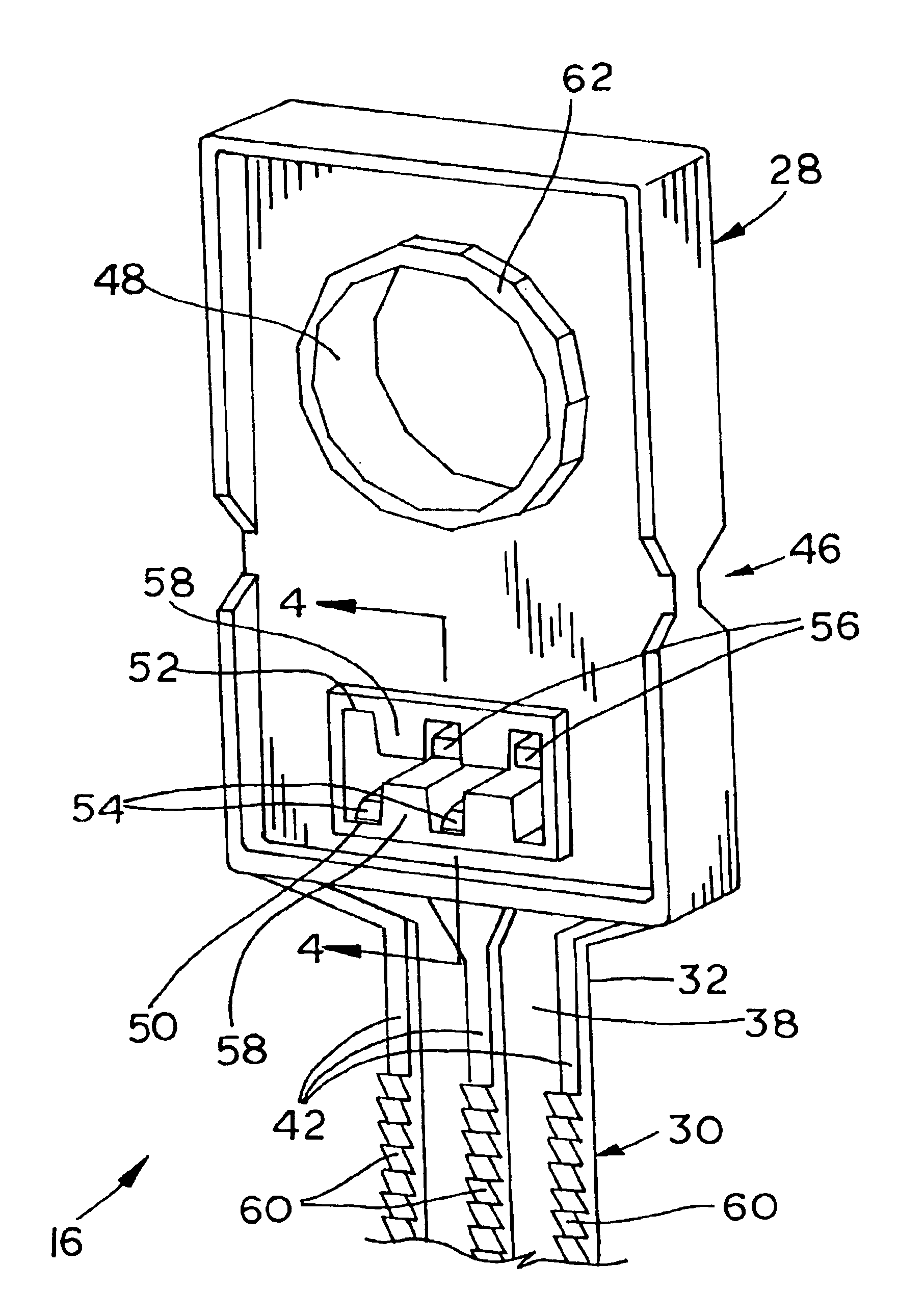
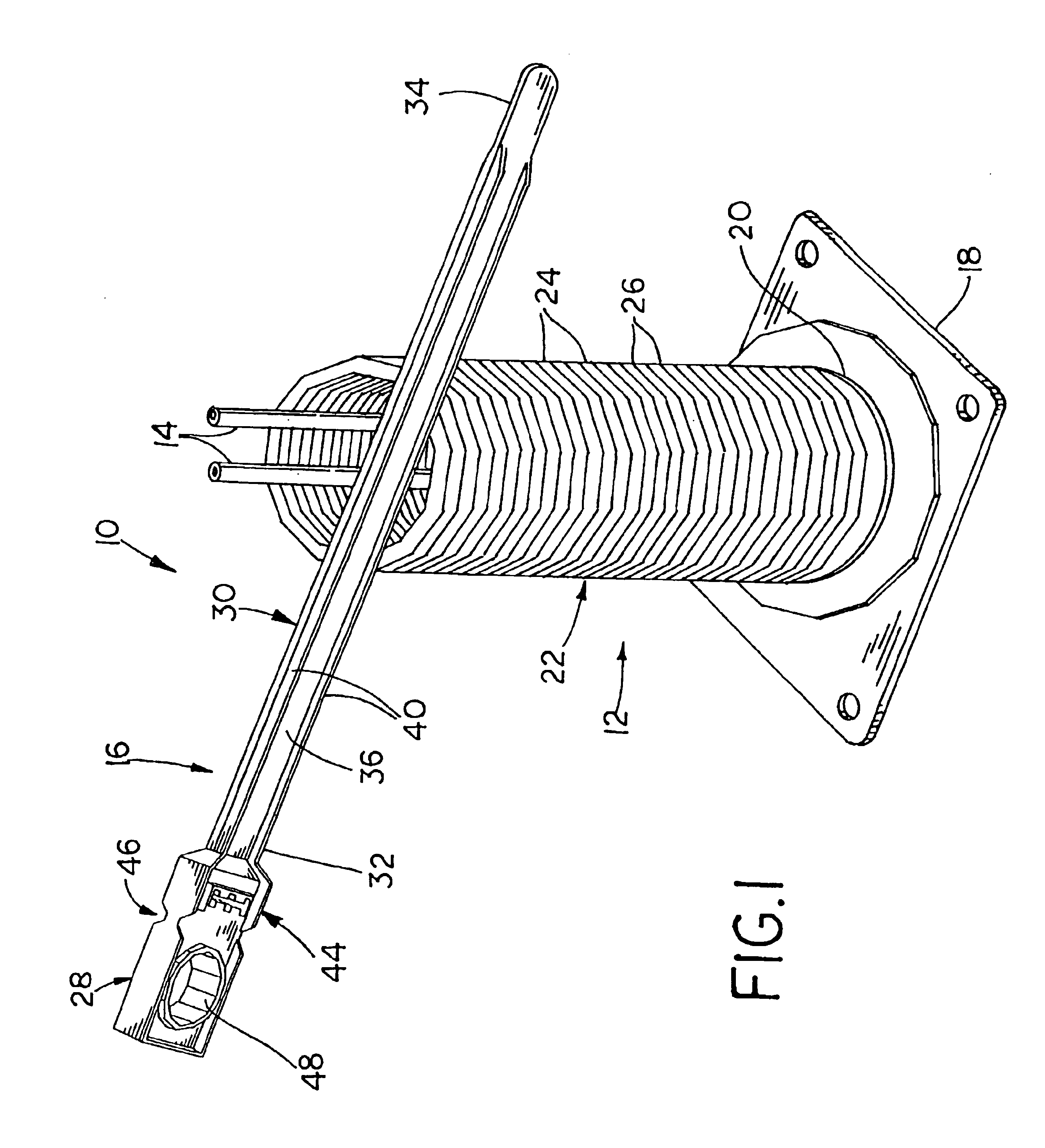
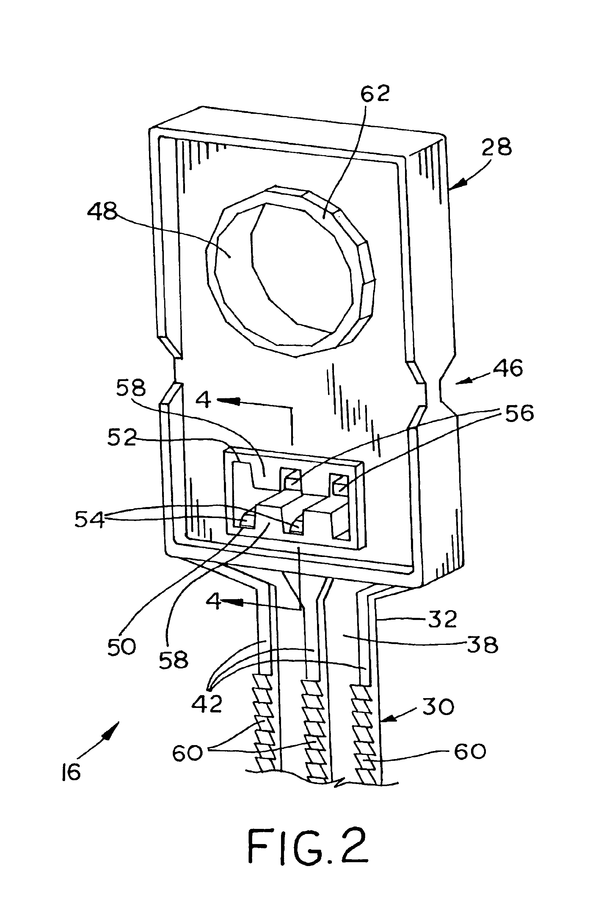
[0021]Referring now to the drawings, and more particularly to FIG. 1, there is shown an embodiment of an electrical assembly 10 of the present invention, which generally includes an electrical convoluted tubing 12, a plurality of electrical conductors 14 and an electrical tie 16. Electrical assembly 10 generally is used for routing electrical conductors 14 form one physical location to another, while at the same time inhibiting mechanical wear to electrical conductors 14 and routing electrical conductors 14 in an aesthetically appealing manner. Electrical assembly 10 may be used for any suitable application, such as household or commercial appliances, engines, lighting systems, etc.

[0022]Electrical conductors 14 may be of any suitable number, size or configuration, depending upon the particular application. For example, electrical conductors 14 may be in the form of individual, insulated conductors (as shown in FIG. 1), a multi-conductor cable, power and / or data conductors, etc.

[002...


PUM


Abstract

An electrical assembly includes an electrical convoluted tubing, at least one electrical conductor and an electrical tie. The electrical convoluted tubing includes an outer surface having a plurality of generally parallel, annular convolutions defining respective grooves therebetween. Each groove has a width. The at least one electrical conductor is positioned within the tubing. The electrical tie is positioned around the tubing and includes a head and an elongate strap. The elongate strap has opposing sides and an end. The end is attached to the head. At least one of the sides has at least one longitudinally extending rib, with each rib having a width which is less than the groove width.

Description

BACKGROUND OF THE INVENTION[0001]1. Field of the Invention[0002]The present invention relates to electrical ties, and, more particularly, to electrical ties used to hold wires, cables, tubing and other elongate electrical elements together.[0003]2. Description of the Related Art[0004]Convoluted tubing in an electrical assembly is used to carry electrical conductors from one location to another and protect the electrical conductors from damage caused by electrical contact such as may occur during impact or vibration. Electrical convoluted tubing typically includes a plurality of generally parallel, annular convolutions which allow the tubing to be flexed as it extends from one location to another. The tubing may include a longitudinal split along one side thereof allowing the electrical conductors to be inserted or removed therefrom.[0005]To prevent the convoluted tubing from being physically damaged and thereby possibly damage the electrical conductors therein, it is also known to c...

Claims


Application Information

Patent Timeline
Patent Type & Authority Patents(United States)
IPC IPC(8): B65D63/10
CPCB65D63/1081Y10T24/1498
Inventor GARVER, SCOTT A.
Owner GROUP DEKKO
Why Eureka
Try Eureka