Mooring robot

a mooring robot and robot technology, applied in the field of mooring, can solve the problems of complex mooring robot control, fore and aft movement and vertical movement of the vessel, and accurately determining the position of the attachment elements, and achieve the effects of efficient operation, efficient use of limited space, and economic construction

Inactive Publication Date: 2005-09-06
CAVOTEC MOORMASTER
View PDF26 Cites 15 Cited by
  • Summary
  • Abstract
  • Description
  • Claims
  • Application Information

AI Technical Summary

Benefits of technology

[0030]This invention provides a mooring robot which is effective in operational use, and compact making efficient use of the limited space available at the front mooring face of a dock. The device may be economically constructed and has an overall simple but structurally efficient design that minimizes manufacturing costs and maximizes performance. It allows for accurate positioning in three dimensions of the vacuum cups and maintains the vacuum cups generally parallel to the hull surface throughout its travel.

Problems solved by technology

A disadvantage of the mooring robot and mooring system described in WO 0162585, however, is that fore and aft movement and vertical movement of the vessel relative to the mooring robot are accompanied by a component of movement athwartship, due to the telescoping arm of the robot being pivotably fixed.
This feature makes accurately determining the position of the attachment elements complicated, and adds to the complexity of controlling the mooring robot.
Also, since the plane of the vacuum cups is not maintained parallel to the surface of the hull with which it engages, additional wear of the vacuum seals may result as the cups are often pivoted as they first engage the hull.
A further disadvantage of this, and like devices, is that the telescopic booms, being subject to significant bending loads, must be relatively massive and that, even with the arms retracted, the device requires significant space at the front mooring face of the dock.
Another solution is to take the longitudinal loads through stay lines, however the stays obstruct a significant area of the face of the dock.

Method used


Image

  • Mooring robot
  • Mooring robot
  • Mooring robot

Examples


Embodiment Construction

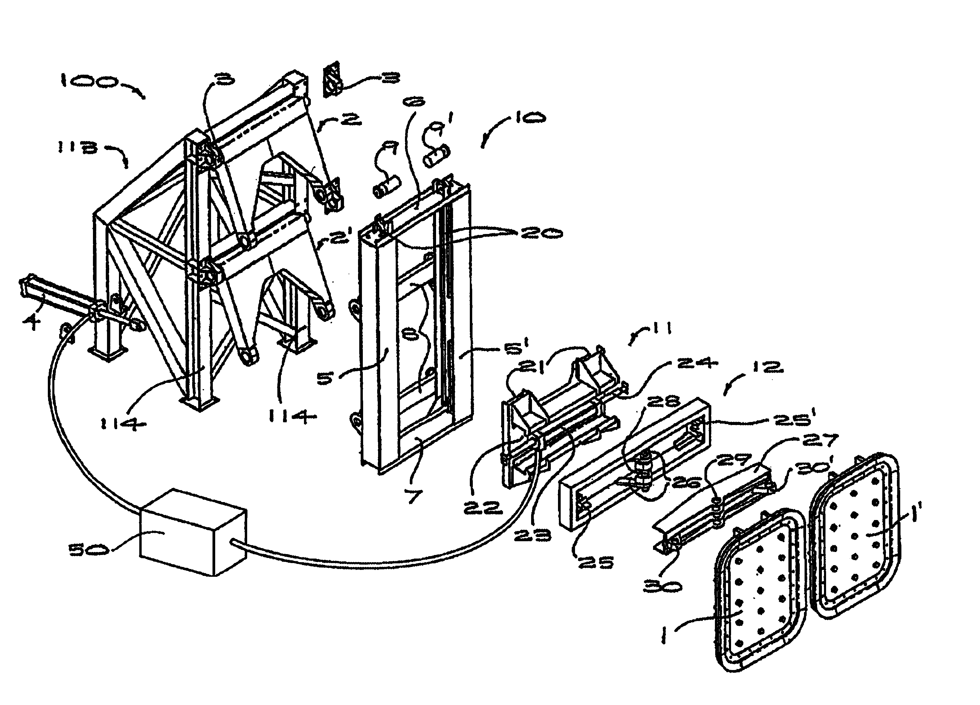
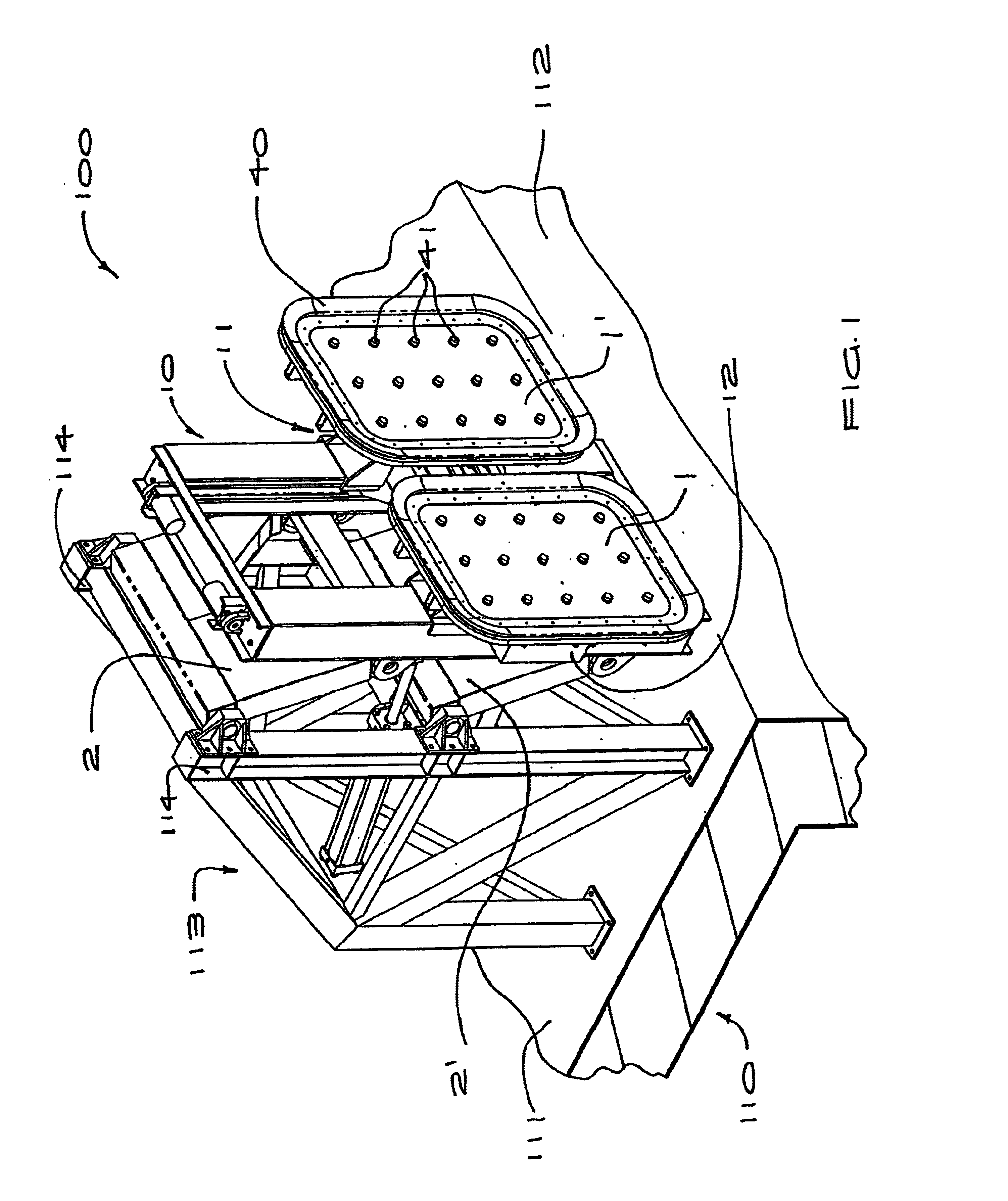
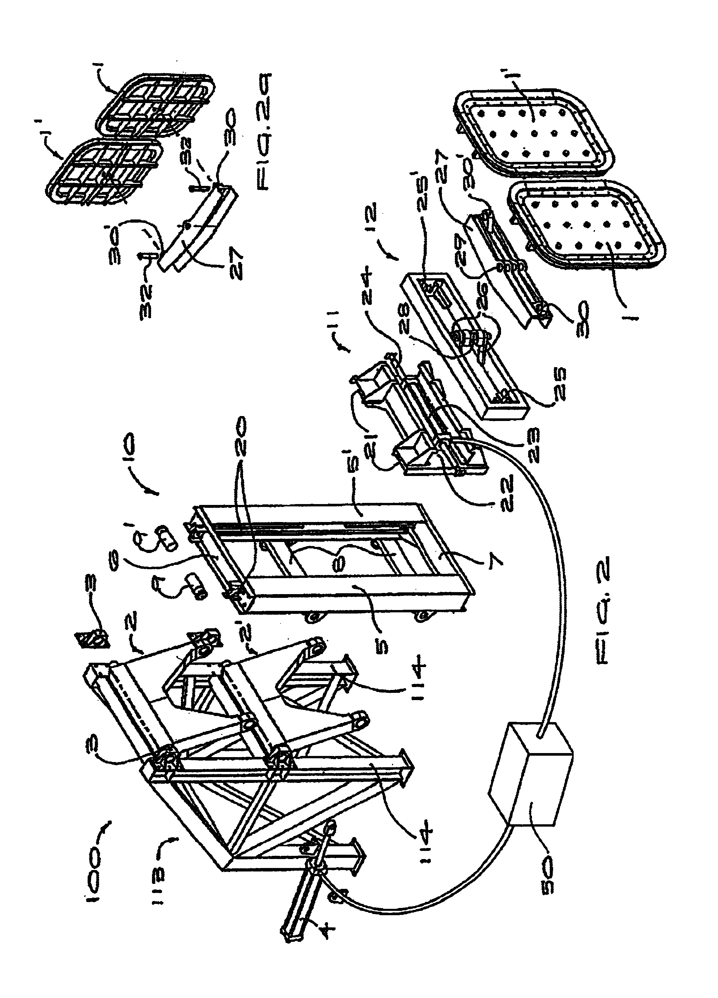
[0037]Referring to FIG. 1, a preferred embodiment of the mooring robot 100 is mounted to a dock 110, fixed adjacent to a front mooring face 112 of the dock. The mooring robot 100 includes a pair of vacuum cups 1, 1′ which are maintained substantially parallel to the plane of the front mooring face 112 for engagement with the hull of a vessel (not shown). The mooring robot 100 is capable of positioning the vacuum cups 1, 1′ in three dimensions, referred to herein as “vertical”, “longitudinal” and “transverse”, wherein “longitudinal” refers to a direction perpendicular to the vertical axis and parallel to the longitudinal axis of the moored vessel or the front mooring face 112 of the dock.

[0038]The mooring robot 100 is fixed to a framework 113 fastened upon a generally horizontal surface 11 of the dock. In alternative embodiments (not shown) the mooring robot 100 may be mounted upon a suitable structure below the surface 111 to maintain the upper surface 11 clear of any obstructions. ...


PUM


Abstract

A mooring robot which can be dock-mounted, and can also include vacuum cups for engagement with the freeboard of a ship. The robot can position the vacuum cups within a three-dimensional operating envelope. A parallel arm linkage having two parallel arms pivoted about respective axes which are parallel to the longitudinal axis of the ship are fixed to the dock for extending and retracting the vacuum cups in the transverse direction. The parallel arms are fixed to a vertical elongate guide to which the vacuum cups are slidably fixed, the parallel arms raising and lowering the vacuum cups and maintaining the guide substantially vertical. The vacuum cups are mounted for sliding in substantially horizontal track aligned parallel with the longitudinal axis of the ship for fore and aft movement of the vacuum cups. A mooring system can also include a plurality of the mooring robots being remotely controlled.

Description

RELATED APPLICATIONS[0001]This application is a national phase entry in the United States of the International Application PCT / NZ02 / 00062 filed Apr. 17, 2002, and claims the benefit of New Zealand Application 511129 filed Apr. 17, 2001.TECHNICAL FIELD[0002]The present invention generally to mooring and more particularly, to robotic mooring devices for mooring large vessels.BACKGROUND ART[0003]When mooring a container ship or similar large vessel to a dock, in order to inhibit damage to the ship or the dock, a mooring robot is generally provided that is adequately strong to resist the forces exerted on it by the action of the wind, waves, passing vessels and tide. The mooring robot also accommodates relative vertical movement between the dock and the ship due to variations in tides and displacement. Further, the mooring robot should permit the connection between the ship and the dock to be made or broken quickly without damage to either the dock or the ship. In view of the large size...

Claims


Application Information

Patent Timeline
Patent Type & Authority Patents(United States)
IPC IPC(8): B63C1/00B63C1/10B63B21/00E02B3/20E02B3/24B25J15/06B25J11/00
CPCB63B21/00B63C1/10E02B3/24B63B2021/006B63C1/00
Inventor MONTGOMERY, PETER JAMESROSSITER, BRYAN JOHN
Owner CAVOTEC MOORMASTER
Why Eureka
Try Eureka