Milk steamer

a technology of steamer and steaming chamber, which is applied in the field of milk steamers, can solve the problems of high heating rate, large electric power consumption, complex control and timing of valve actuation, etc., and achieves the effects of simple overall design, economic construction, and effective and efficient operation

Inactive Publication Date: 2015-04-16
G E W INT CORP
View PDF46 Cites 16 Cited by
  • Summary
  • Abstract
  • Description
  • Claims
  • Application Information

AI Technical Summary

Benefits of technology

[0018]Preferably the changeover valve and vent valve of both moved to and from their normal position substantially simultaneously. By having the changeover valve and vent valve both moved to and from their normal position substantially simultaneously the control of the machine is simplified compared to prior art where delays must be implemented between valve operations.
[0043]This invention provides an automatic milk steamer which is effective and efficient in operational use, and which produces consistent flavour and foam texture. The device may be economically constructed and has an simple overall design that minimizes manufacturing costs and maximizes performance.

Problems solved by technology

On the other hand, thermoblocks provide high heating rates and consequently consume considerable electric power while in operation.
However under certain operating conditions, condensation of steam in the nozzle produces a vacuum that draws milk into the nozzle.
Moreover, complex control and timing of valve actuations is needed.
Automatic steaming devices are known which allow anyone to obtain frothy milk without any skill, however many of these prior art devices have various drawbacks including unsatisfactory or inconsistent flavour and foam texture, lack of versatility, and high complexity and manufacturing costs.

Method used


Image

  • Milk steamer
  • Milk steamer
  • Milk steamer

Examples


Embodiment Construction

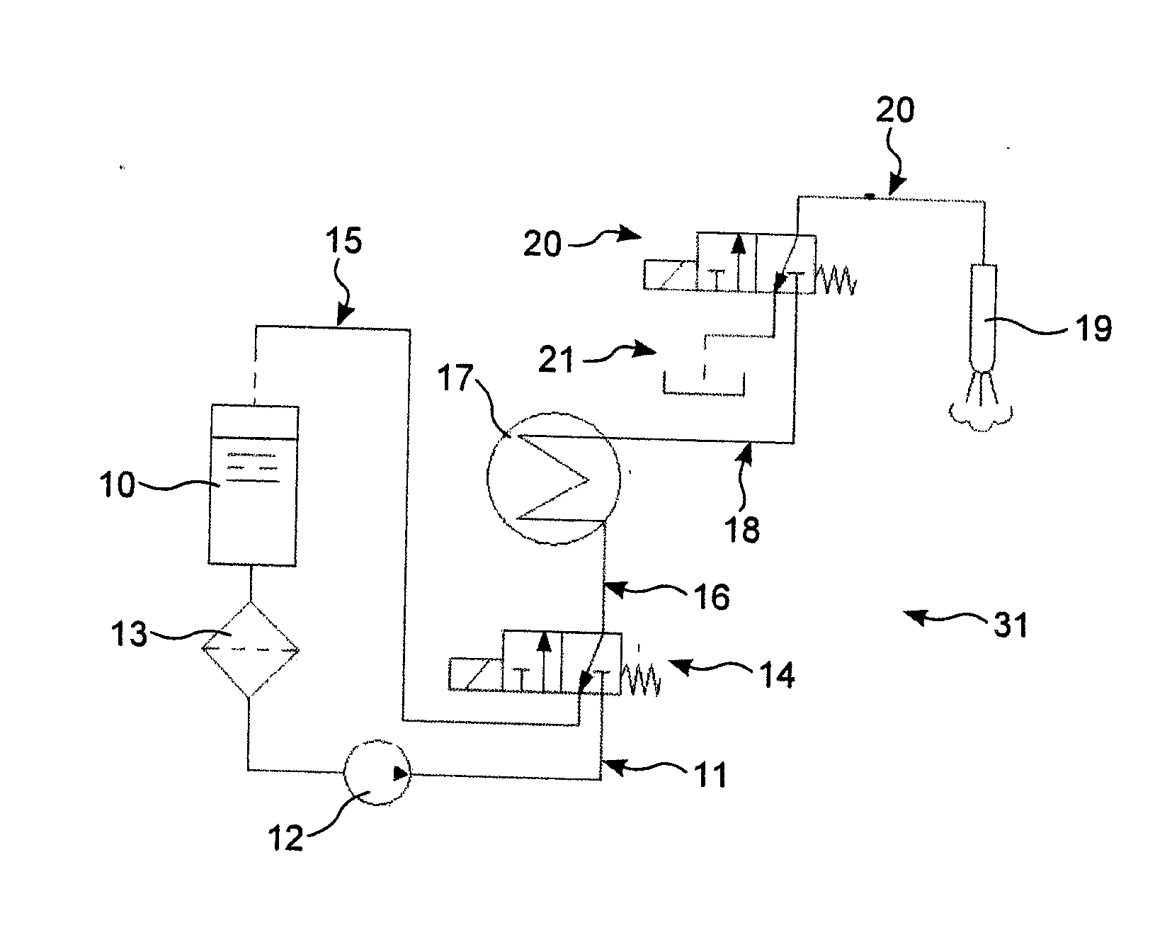
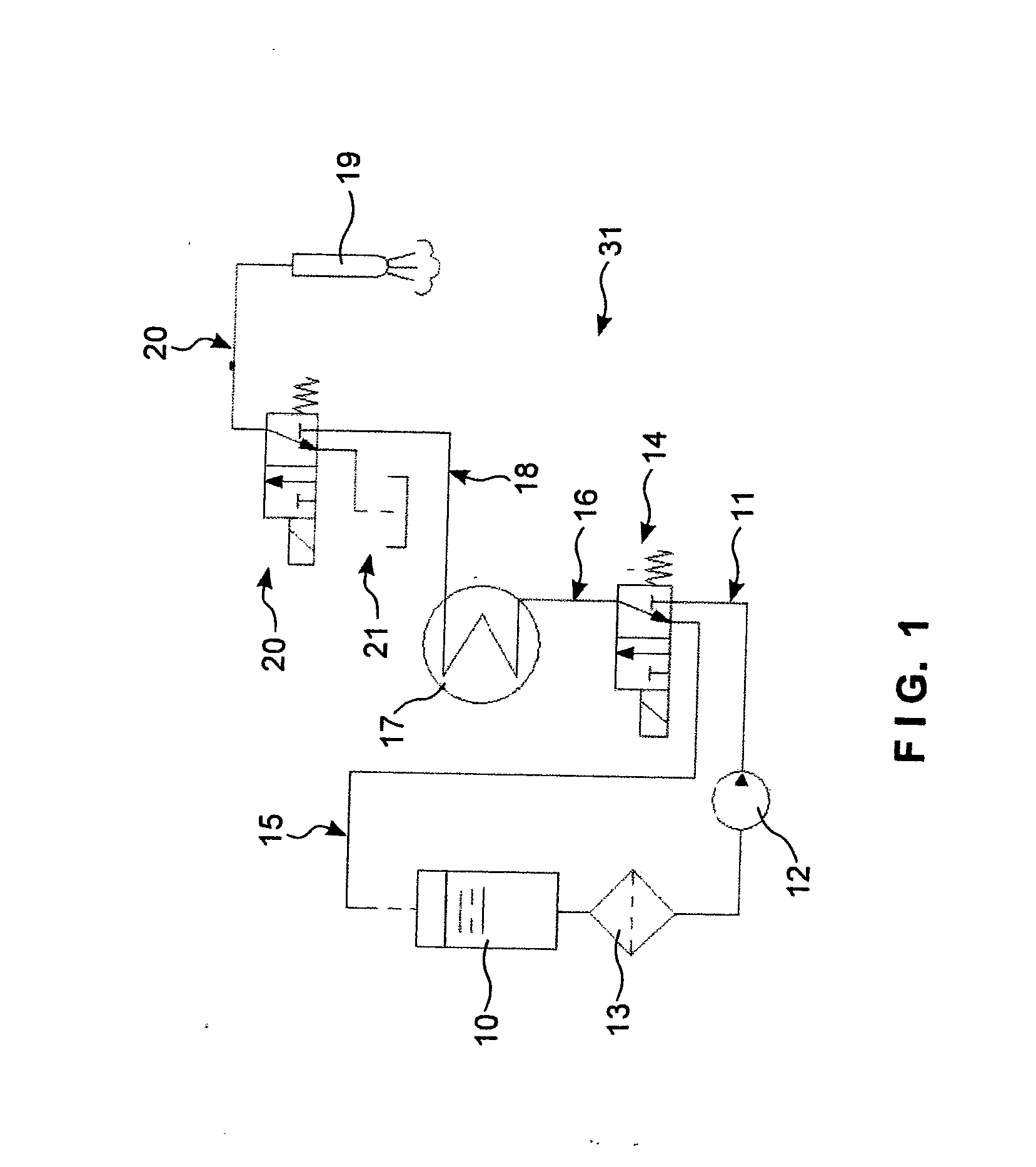
[0047]Referring to FIG. 1, a milk steamer generally comprises steam generator 31 connected to a steam nozzle 19 which, in use, is inserted into a vessel containing the milk to be steamed and foamed. The steam generator 31 includes a water reservoir 10 with a supply line 11 connected to the water reservoir 10 and a pump 12 connected in the supply line 11 for generating a water flow. A filter 13 may be connected in the supply line between the water reservoir 10 and the pump 12. A return line 15 may carry a return flow to the water reservoir 10. A steam-generating thermoblock 17 is supplied with water via a changeover valve 14 that selectively connects an inlet 16 of the thermoblock to the supply line 11. The changeover valve 14 may alternately connect the inlet 16 of the thermoblock to either the supply line 11 or the return line 15. An outlet 18 of the thermoblock is connected via a vent valve 20 to the steam nozzle 19. Also connected to the vent valve 20 is an evacuation outlet 21, ...


PUM


Abstract

In a milk steamer, a changeover valve and a vent valve are connected to the inlet and the outlet of a steam-generating thermoblock to provide ready draining of water, and to mitigate condensation of steam that draws milk into the steam nozzle. In an automatic milk steamer, the height of the steam nozzle above the milk level is automatically set by interaction between a drive mechanism and a liquid level sensor.

Description

TECHNICAL FIELD[0001]The present invention relates to milk steamers and methods for operating such milk steamers.BACKGROUND OF THE INVENTION[0002]The invention generally relates to a milk steamer in which water is heated in a so-called thermoblock in order to produce steam. The term “thermoblock” as used herein refers to a heat exchanger in which water is heated (e.g. by resistance elements) while it is pumped. In contrast, in a boiler the steam is dispensed only after the heating is finished. Generally boilers have a much higher thermal inertia with a resulting slower response to heat inputs. On the other hand, thermoblocks provide high heating rates and consequently consume considerable electric power while in operation.[0003]A milk steamer according to the present invention is provided with a steam outlet, as in the form of a nozzle, for steaming milk. The milk steamer may be a stand-alone device, or part of a larger machine, such as a coffee machine.[0004]EP1764014 describes mil...

Claims


Application Information

Patent Timeline
Patent Type & Authority Applications(United States)
IPC IPC(8): A47J31/44
CPCA47J31/4489Y10T137/6416
Inventor YIP, THOMAS CHUNG LIK
Owner G E W INT CORP
Why Eureka
Try Eureka