Motorised hair styling iron

a motorised, iron technology, applied in curling irons, curling tongs, hair equipments, etc., can solve the problems of variable processing results, damage to hair, and insufficient hair format, and achieve the effects of simple design, economic construction, and effective processing

Inactive Publication Date: 2013-01-31
KENFORD INDAL
View PDF22 Cites 14 Cited by
  • Summary
  • Abstract
  • Description
  • Claims
  • Application Information

AI Technical Summary

Benefits of technology

[0027]This invention provides hair iron which is particularly effective in use with the above-described method. The iron may be economically constructed and has an overall simple design which minimizes manufacturing costs and maximizes performance, allowing the user to draw the tool through the hair with a generally constant hair-gripping force.

Problems solved by technology

Some of the drawbacks with the prior art hair irons are that the processing results can be variable, if the operation is performed too fast, the processing time is too short and, therefore, the hair is not properly formatted, while moving too slowly can damage the hair by overheating.
A new user unfamiliar with the iron may have difficulty in accurately controlling the hair-gripping forces that vary with the clamping pressure between the heating body and hair.
As a tool with opposing smooth and hard clamping faces is drawn through the hair any variation in the user's hold on the tool produces a variable contact pressure that can cause discomfort, as the hair is pulled unevenly.
The resulting treatment of a lock of hair may also produce an uneven appearance.
One way in which this issue has been addressed in old hair irons is by providing one of the jaws with a brush or comb for gripping the hair, however such a brush or comb makes the tool less compact and can restrict the manner in which the tool can be used for different operations, such as curling and straightening.

Method used


Image

  • Motorised hair styling iron
  • Motorised hair styling iron

Examples


first embodiment

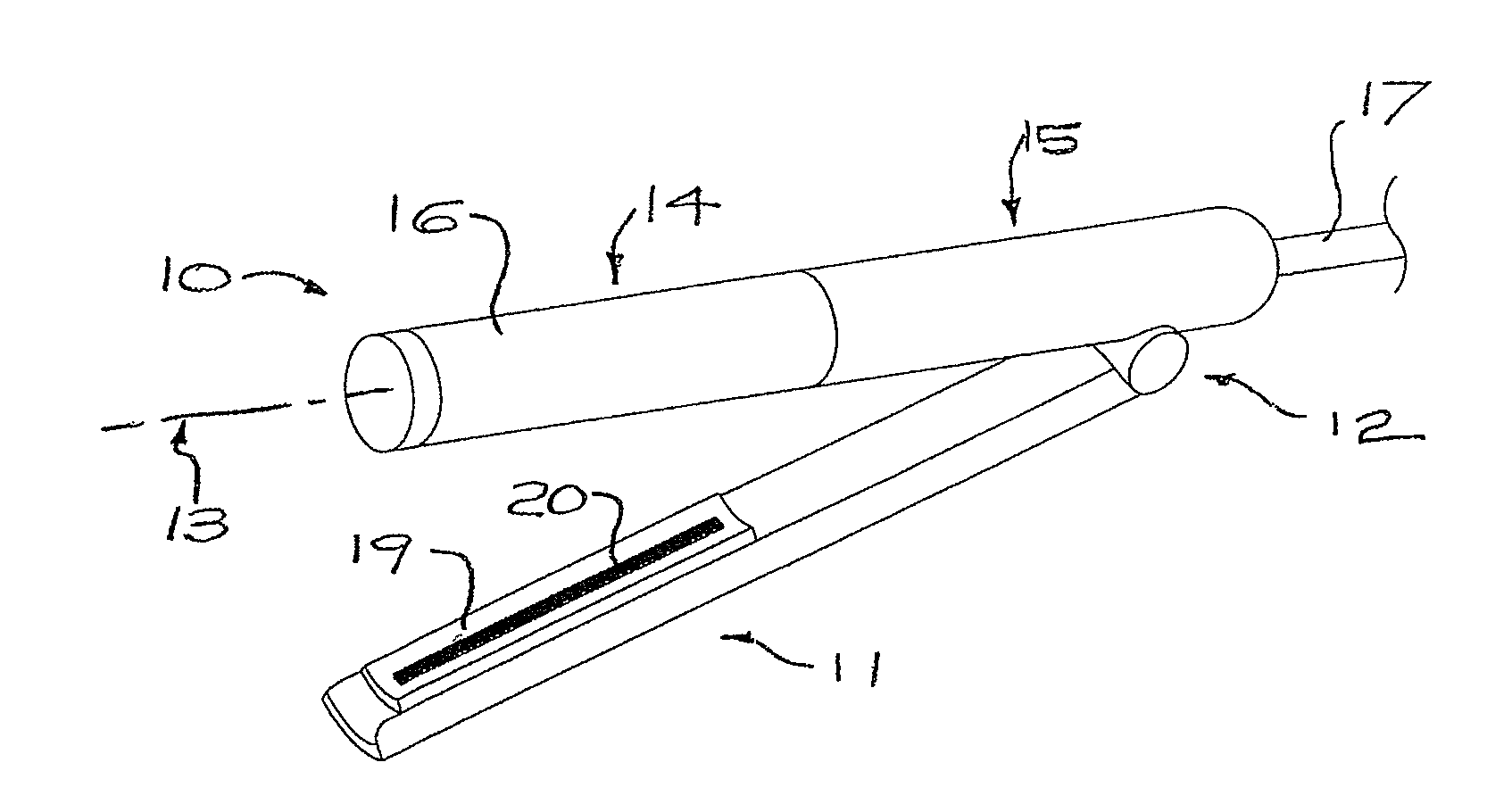
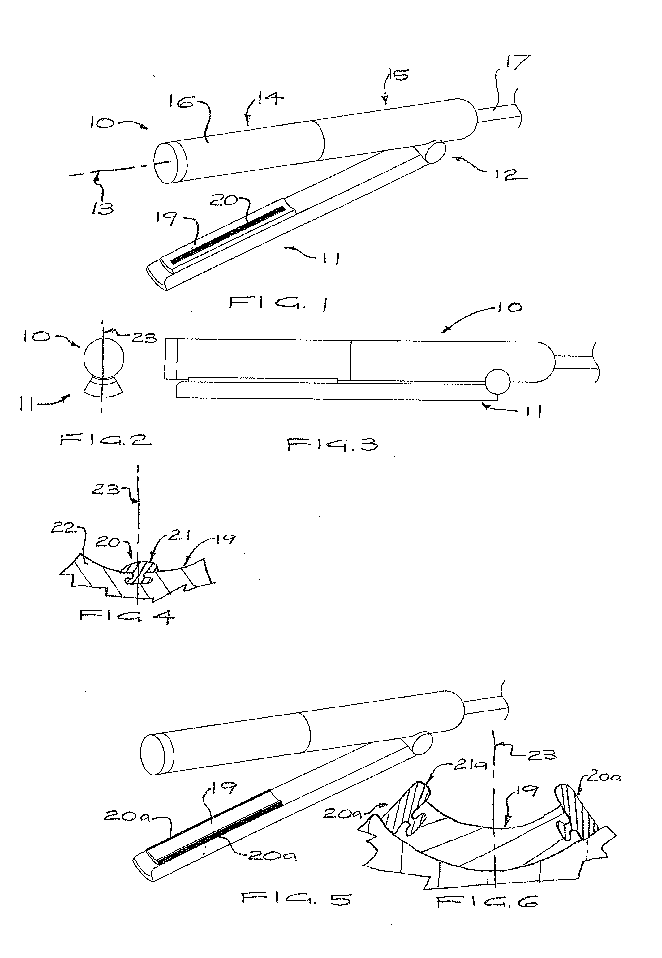
[0035]Referring to the drawings, FIG. 1 illustrates a hand held electric hair iron having first and second elongate jaws 10, 11 joined at respective proximal parts disposed near their longitudinal ends by a transverse hinge 12, shown in an open position. Both jaws 10, 11 are of hollow construction, with the first jaw 10 including a barrel 14 disposed at its outer end and a coaxial handle section 15 at its inner end. The barrel 14 has a first longitudinal axis 13 and a substantially cylindrical hair-engaging surface 16.

[0036]In the preferred embodiments illustrated, the barrel 14 is heated by an internally enclosed resistive element (not shown). Further, the barrel 14 is motor-driven to rotate about the longitudinal axis 13, or to vibrate, either generally omni-directionally or linearly or rotationally along / about an axis. Motorised hair irons having a jaw driven to rotate or vibrate are known from the prior art, and it will be understood that this can be achieved in a number of diff...

second embodiment

[0040]the second jaw is shown in FIGS. 5 and 6, in which a pair of parallel, generally coextensive, elastomeric ribs 20a are provided, each disposed adjacent opposing longitudinal edges of the hair-engaging surface 19, such that their exposed faces 21a project beyond the surface 19. The ribs 20a are disposed symmetrically on opposing sides of the central plane 23.

[0041]In preferred embodiments the width of the rib 20, 20a is between 2% and 20% of the width of the concave face 19, most preferably between 5% and 10% of the width of the face 19. Ribs 20, 20a of silicon rubber having a hardness of 40 Shore A has been found to provide good performance, but satisfactory performance can be obtained with a hardness between 30 Shore A and 50 Shore D.

[0042]In use, a lock of hair is wound in a loop about the elongate barrel 14, the user grasping the jaws to clamp the lock of hair between the faces 16, 19. In this manner the hair is pressed against the rib(s) 20, 20a while it is softened by the...


PUM


Abstract

A hair styling iron includes a pair of hinged elongate jaws having complementary hair-engaging surfaces configured to hold and engage hair between the surfaces. The iron is motorised for rotating or vibrating at least one of the jaws. At least one elastomeric rib extends along one of the hair-engaging surfaces, and allows the user to readily modulate the hair-gripping force.

Description

TECHNICAL FIELD[0001]The present invention relates to hair styling irons, particularly electric appliances for hair curling or straightening, having one member motor driven to rotate or vibrate.BACKGROUND OF THE INVENTION[0002]One type of known hand-held electric hair curling or straightening iron use two jaws or arms, at least one of which is heated, with the other cooperating to hold hair in contact with the first, and being moveable from an open position allowing the insertion of hair to a closed position to put the hair in contact with the heater.[0003]Some of the drawbacks with the prior art hair irons are that the processing results can be variable, if the operation is performed too fast, the processing time is too short and, therefore, the hair is not properly formatted, while moving too slowly can damage the hair by overheating. Operation of these irons requires the user to carefully manipulate the two jaws. A new user unfamiliar with the iron may have difficulty in accurate...

Claims


Application Information

Patent Timeline
Patent Type & Authority Applications(United States)
IPC IPC(8): A45D1/02
CPCA45D1/04A45D2200/207A45D2/001A45D1/10
Inventor KEONG, WAI HO MICHAELWAN, WAI KEUNG KENT
Owner KENFORD INDAL
Why Eureka
Try Eureka