Backpressure adapter pin and methods of use

a backpressure adapter and pin technology, applied in the field of backpressure adapter pins, can solve the problems of time-consuming and expensive procedures

Inactive Publication Date: 2005-09-06
STINGER WELLHEAD PROTECTION
View PDF27 Cites 88 Cited by
  • Summary
  • Abstract
  • Description
  • Claims
  • Application Information

AI Technical Summary

Problems solved by technology

This is an expensive and time consuming procedure that requires the use of wireline equipment to set the plug, as well as to remove it.
However, if the tubing hanger is removed, the plug is removed with it, leaving the tubing string open to atmosphere.

Method used


Image

  • Backpressure adapter pin and methods of use
  • Backpressure adapter pin and methods of use
  • Backpressure adapter pin and methods of use

Examples


Embodiment Construction

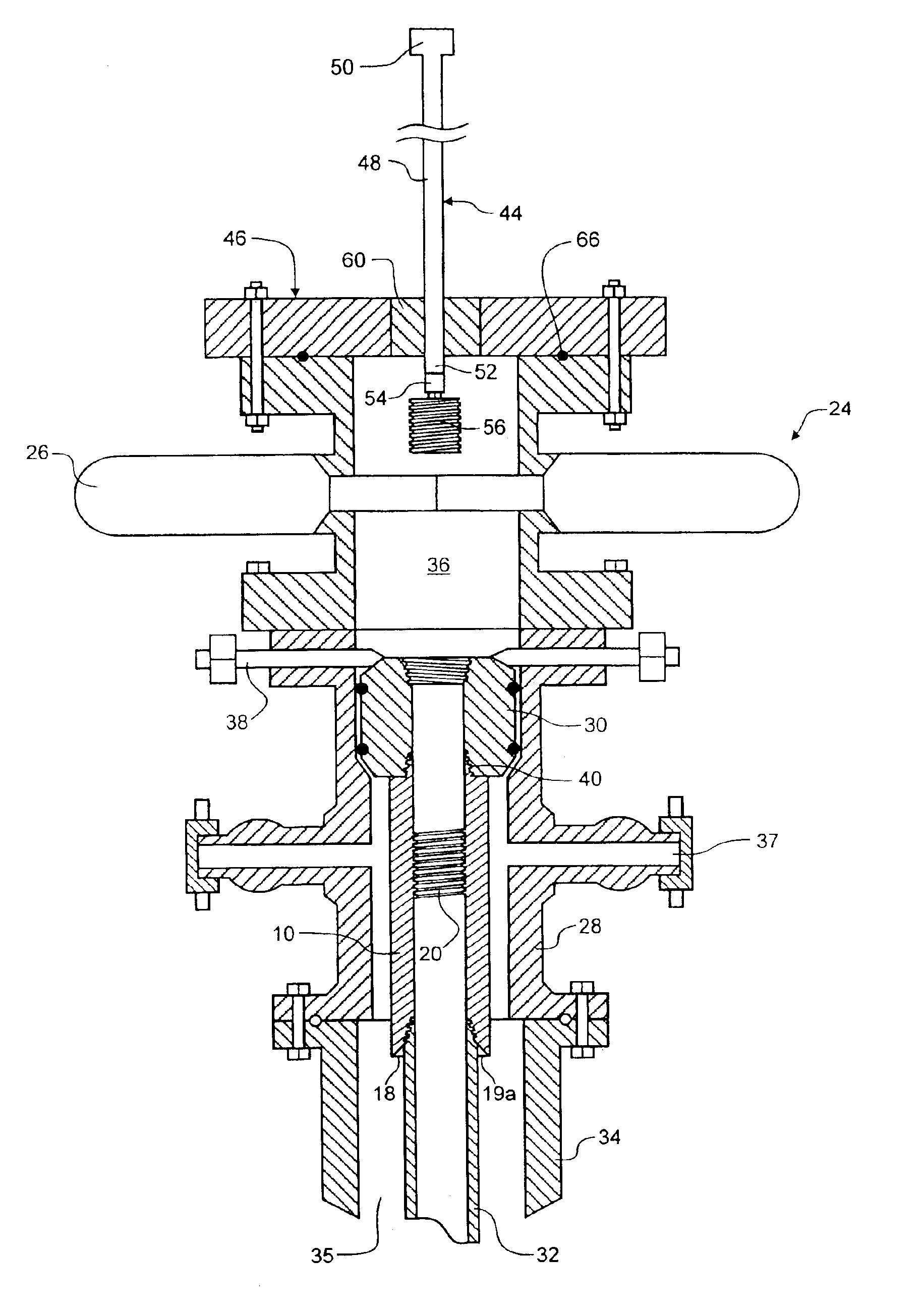
[0029]The invention provides a method for permitting the setting of a backpressure plug below a tubing hanger within reach of a backpressure plug tool. The method is facilitated by backpressure pin threads in a backpressure adapter pin, which may be a tubing collar, for example. The backpressure pin threads may also be integrated with the tubing string below the tubing hanger, so that the tubing hanger may be removed or landed without setting or retrieving a wireline plug. The methods permit setting the backpressure plug, and removing a tubing hanger without the use of a wireline tool.

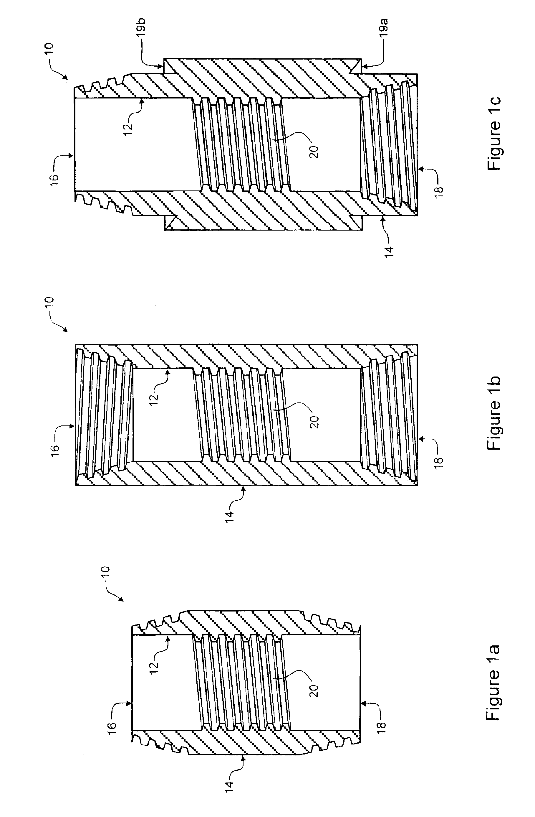
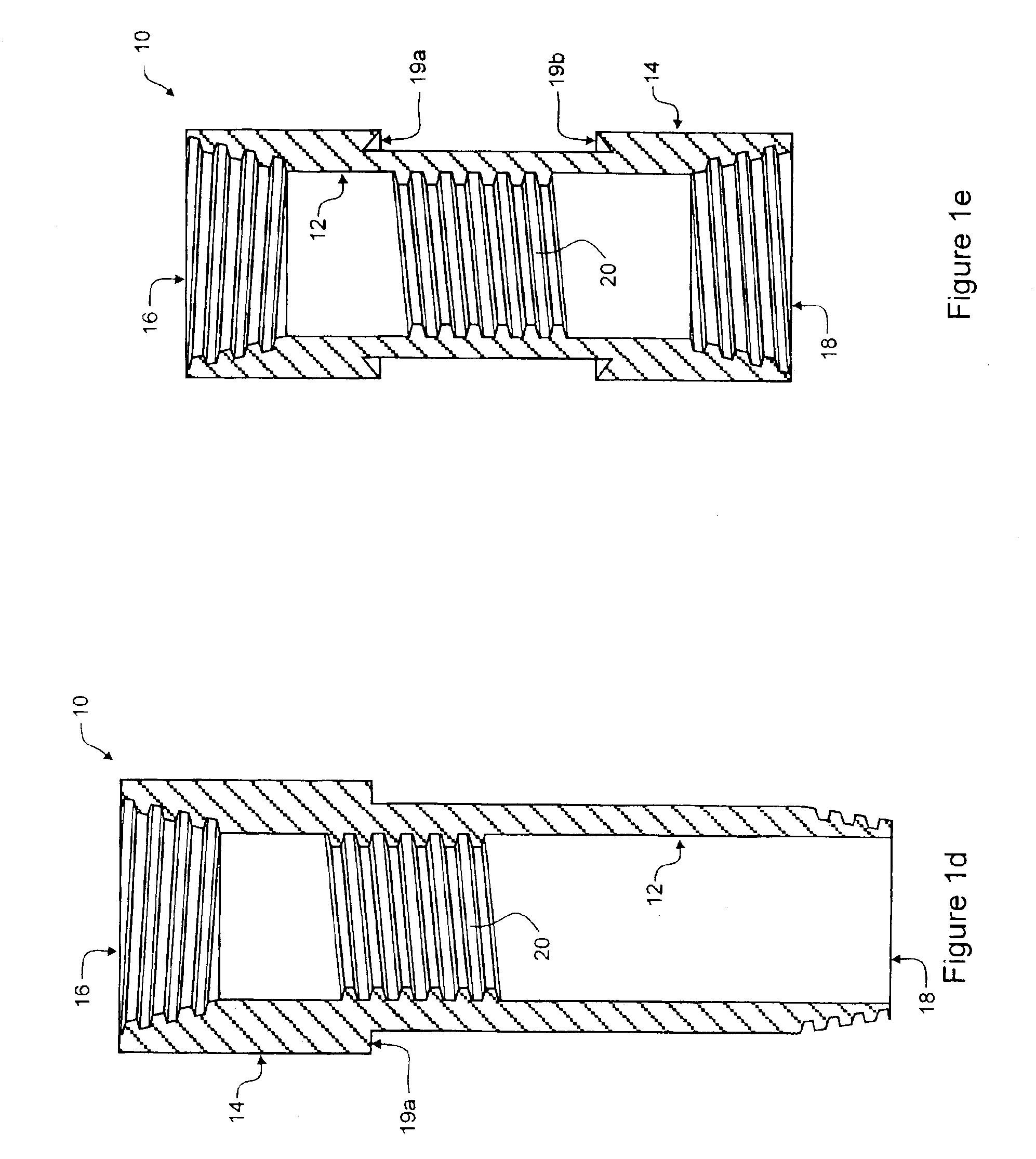
[0030]As illustrated in FIGS. 1a-e, the backpressure adapter pin 10 is a tubing joint having substantially cylindrical inner 12 and outer 14 walls, a top end 16 and a bottom end 18. The top end 16 is adapted to be connected to a tubing hanger, or to a pup joint connected to the tubing hanger. The bottom end 18 is adapted to be connected to a tubing string. As illustrated in FIG. 1a the top end 16 and b...


PUM


Abstract

A tubing assembly including a tubing string and tubing hanger provides a fluid passage with backpressure threads for securing a backpressure plug in a fluid-tight seal below the tubing hanger, so that the tubing hanger can be removed from the tubing string. The back pressure threads are preferably incorporated in a backpressure adapter pin connected between the tubing string and the tubing hanger. The adapter pin may also incorporate external weight-bearing shoulders for snubbing and / or suspending the tubing assembly. The backpressure plug is inserted or removed using a backpressure plug tool that slides through a packing in a pressurized casement that maintains pressure in an axial passage through a control stack of the wellhead.

Description

CROSS-REFERENCE TO RELATED APPLICATIONS[0001]This application is a divisional of U.S. patent application Ser. No. 10 / 336,911 filed Jan. 6, 2003.MICROFICHE APPENDIX[0002]Not Applicable.TECHNICAL FIELD[0003]The invention relates to the field of oil and gas well operations, and more particularly to a backpressure adapter pin and method of using the adapter pin to facilitate servicing operations for oil and gas wells.BACKGROUND OF THE INVENTION[0004]Modern methods for stimulating hydrocarbon flow in oil and gas wells, has increased demand for well servicing knowledge and equipment. Common well servicing operations include removing and installing spools, valves, blowout preventors and other elements in a control stack on the wellhead, inserting downhole tools into the well, and / or injecting high-pressure well stimulation fluids. Modern equipment permits many of these operations to be performed without killing the well. This is advantageous because killing fluids are expensive and have th...

Claims


Application Information

Patent Timeline
Patent Type & Authority Patents(United States)
IPC IPC(8): E21B33/03E21B33/12E21B33/04E21B33/068
CPCE21B33/04E21B33/068E21B33/12
Inventor DALLAS, L. MURRAY
Owner STINGER WELLHEAD PROTECTION
Why Eureka
Try Eureka