
Fuel-water separator unit with parallel flow

a technology of fuel-water separator and fluid flow, which is applied in the direction of filter cartridges, filtration separation, separation processes, etc., can solve the problems of clogging of filter cartridges in upward direction, rapid reduction of filter life, and progression of clogging of filters, so as to reduce back flushing of contaminants.

Inactive Publication Date: 2005-09-06
FLEETGUARD INC
View PDF52 Cites 49 Cited by
  • Summary
  • Abstract
  • Description
  • Claims
  • Application Information

AI Technical Summary

Benefits of technology

"The present invention concerns a filter assembly that includes a housing with a filter cartridge cavity. The filter cartridge includes a filter element to filter fluid, with a first end plate and a second end plate to seal with the housing. The filter cartridge divides the cavity into an outer cavity and an inner cavity, with the inner post extending from the second end to the first end of the filter element. The filter assembly also includes a coolant passageway to control the temperature of the fluid, with a thermostat positioned in the coolant passageway to determine the temperature of the fluid based on coolant temperature. The invention also concerns a filter assembly with a filter cap enclosing the filter housing and containing an additive container to supply additive to the fluid. The technical effects of the invention include improved filtering efficiency, temperature control, and the ability to add additives to the fluid."

Problems solved by technology

As should be appreciated, this uneven pressure differential distribution allows the bottom filter media to become plugged first, such that the filter cartridge progressively clogs in an upward direction.
Overt time, the effective surface area of the cartridge that can filter fluid reduces, thereby hastening the progression of clogging of the filter such that the life of the filter is rapidly reduced.
Another disadvantage of the counter flow filter design, especially with fuel filters, is that the counter fluid flow disturbs the water in the filter's sump that has been already separated from the fuel such that the water and any contaminants in the water are reintroduced into the fuel.
This reintroduction of water reduces fuel-water separation efficiency as well as the overall filtering efficiency of the filter cartridge.
Another problem faced with fuel filters is associated with contaminated, unfiltered fuel in the cartridge draining back into the system.
Once the engine is turned off, the unfiltered fluid picks up additional contaminants from the filter media and back flushes these contaminants into the fuel system, thereby further contaminating the fuel system.
However, such check valves can stick and be rendered useless if not properly maintained.
Moreover, the check valves increase both the manufacturing and maintenance costs associated with the filter.
If the temperature of the diesel fuel becomes too low, the diesel fuel can become highly viscous, thereby preventing the engine from operating properly.
Over time, this seal can deteriorate such that the seal leaks and contaminates the fuel system, which can be detrimental to engine performance.
However, over or under supply of the fuel additive can adversely affect engine performance.
Controlling the supply rate of fuel additives, while critical, can be rather difficult.
Typical fuel additive systems require complicated valving and other systems for controlling the supply rate of the additive.

Method used


Image

  • Fuel-water separator unit with parallel flow
  • Fuel-water separator unit with parallel flow
  • Fuel-water separator unit with parallel flow

Examples


Embodiment Construction

[0018]For the purposes of promoting an understanding of the principles of the invention, reference will now be made to the embodiments illustrated in the drawings and specific language will be used to describe the same. It will nevertheless be understood that no limitation of the scope of the invention is thereby intended, such alterations and further modifications in the illustrated device, and such further applications of the principles of the invention as illustrated therein being contemplated as would normally occur to one skilled in the art to which the invention relates.

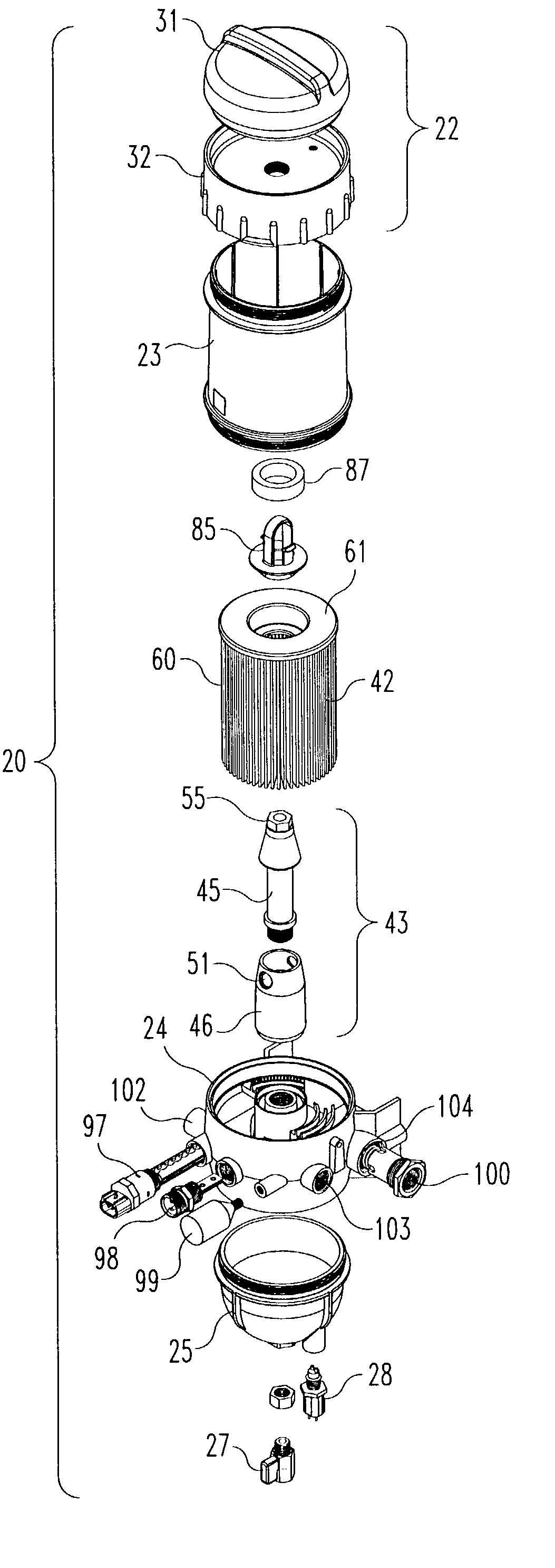
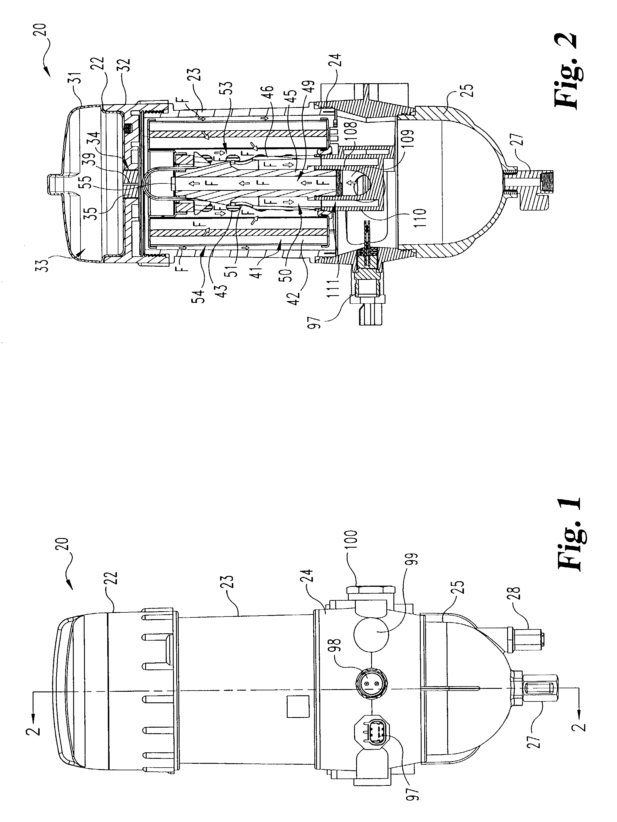
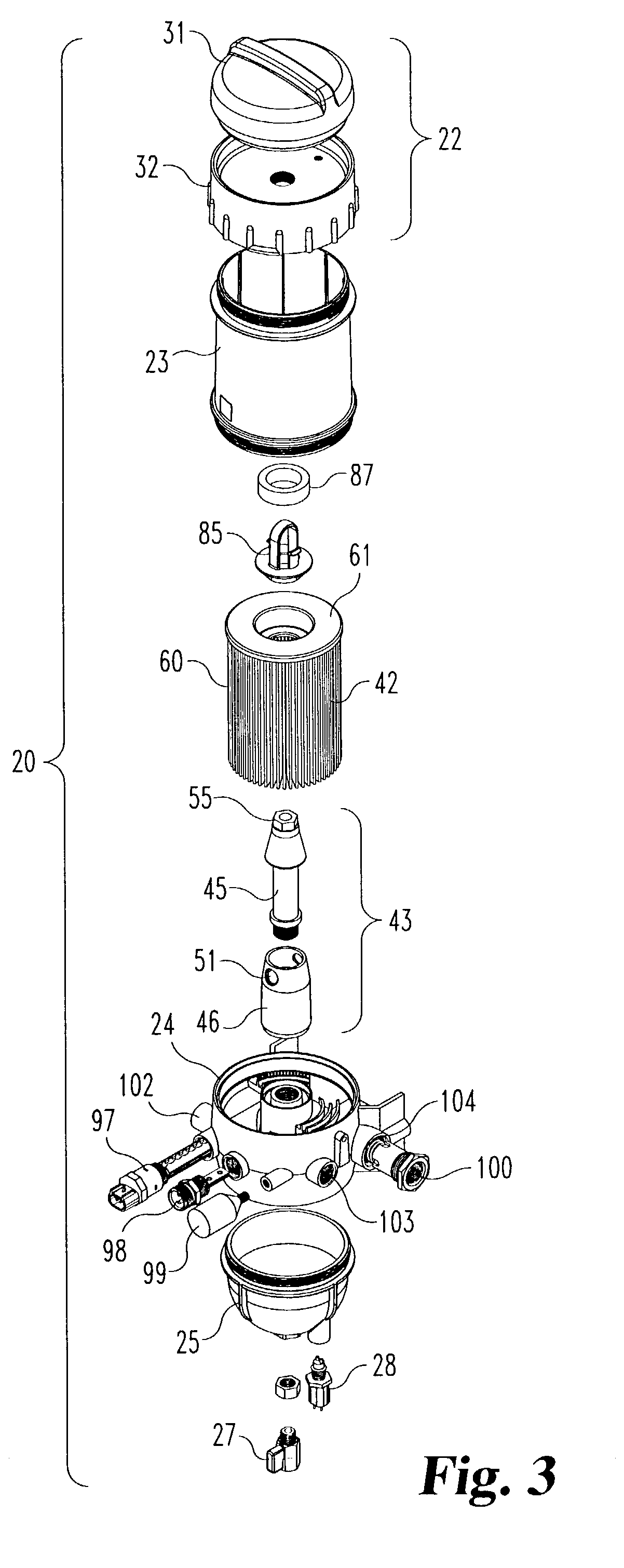
[0019]A filter assembly 20 according to one embodiment, among others, of the present invention is illustrated in FIGS. 1–3. The filter assembly 20 will be described with reference to a fuel filtering environment, but it should be appreciated that many features described herein can be applied to other fields in which other types of fluids, such as oil, are filtered. As shown in FIG. 1, the filter assembly 20 inc...


PUM

PropertyMeasurementUnit
temperatureaaaaaaaaaa
pressureaaaaaaaaaa
differential pressureaaaaaaaaaa

Abstract

A filter assembly includes a housing and an inner post with a fluid inlet passage extending in the housing. An outer post surrounds the inner post to define a fluid outlet passage. A filter cartridge is received around the inner post and the outer post. The filter cartridge includes a filter element. A first endplate, which defines a first opening, is attached to a first end of the filter element. A first seal is received in the first opening to seal between the inner post and the first endplate. A second endplate, which defines a second opening, is attached to a second end of the filter element. A seal is received in the second opening to seal the outer post with the second endplate. The housing and the filter cartridge define an outer cavity. The fluid inlet passage opens into the outer cavity to minimize back flushing of contaminants.

Description

REFERENCE TO RELATED APPLICATION[0001]The present application is a Continuation-In-Part patent application of U.S. patent application Ser. No. 10 / 243,361 filed Sep. 13, 2002 entitled FILTER CARTRIDGE WITH FLOATING SEAL, which is hereby incorporated by reference in its entirety.BACKGROUND OF THE INVENTION[0002]The present invention generally relates to filter assemblies and more specifically, but not exclusively, concerns a filter with parallel fluid flow.[0003]Filters are used in a wide variety of environments in order to filter particulate matter out of fluid. For instance, filters are used to filter particulates from both oil and fuel in engines in order to prolong the life of the engine. Conventional filter cartridge designs usually incorporate a cylindrical-shaped filter cartridge that defines a center post cavity in which a center post is received. In one typical flow pattern, the fluid is filtered by flowing through the cartridge from the outside of the cartridge to the inside...

Claims


Application Information

Patent Timeline
Patent Type & Authority Patents(United States)
IPC IPC(8): B01D36/00B01D29/21B01D29/13
CPCB01D29/21B01D36/003B01D29/902B01D29/96B01D2201/291B01D2201/34B01D2201/316
Inventor JIANG, ZEMINCLEVENGER, JOHN
Owner FLEETGUARD INC
Learn More