Arrangements to detect and respond to disturbances in electrical power systems

a technology for electrical power systems and disturbances, applied in emergency power supply arrangements, emergency protective arrangements for limiting excess voltage/current, nuclear elements, etc., can solve the problems of inability to accurately and quickly detect, unsatisfactory for the purpose of continuing to supply load, and relatively slow and desensitized responses, so as to avoid undesirable current flow and minimize undesirable transfer delays

Inactive Publication Date: 2005-09-06
S&C ELECTRIC
View PDF3 Cites 8 Cited by
  • Summary
  • Abstract
  • Description
  • Claims
  • Application Information

AI Technical Summary

Benefits of technology

[0008]Accordingly, it is a principal object of the present invention to provide arrangements and methods for accurately detecting and responding to disturbances in electrical power systems via integration based on a comparison of actual source voltage to a varying reference.
[0011]It is a further object of the present invention to provide an arrangement for detecting and responding to voltage disturbances by transferring a load to an alternate source of power via the use of a high-speed source-transfer switching system that both avoids undesirable current flow between sources and minimizes undesirable transfer delays.
[0014]These and other objects of the present invention are efficiently achieved by arrangements and methods for detecting and responding to disturbances in electrical power systems. In a preferred arrangement, an integration is initiated that is based on a comparison of actual voltage of a source and a reference voltage. When the integration exceeds a predetermined value, the source is considered unreliable. Also in a preferred arrangement, a determination is made as to whether or not the disturbance is a downstream fault condition. For example, this is useful for applications where a transfer is made from a first source to a second source when predetermined disturbances are detected. In this manner, the transfer of the load to a second source is avoided which would continue the supply of the downstream fault. Additionally, the arrangement distinguishes between various degrees of disturbances to permit appropriate response based on the severity and type of disturbance. For example, a first immediate response, i.e. without intentional delay, is provided for more severe disturbances while a second delayed response is provided for less severe disturbances. The control arrangements transfers the load to an alternate source of power via the use of a high-speed source-transfer switching system that both avoids undesirable current flow between sources and minimizes undesirable transfer delays.

Problems solved by technology

Various types of voltage disturbances, such as sags, swells and transients, can occur on electrical power lines which are undesirable to continued proper operation of the various loads on the electrical system.
In situations where the voltage disturbance is caused by a fault, it is undesirable to continue supplying the load where the fault is downstream of the source.
While these arrangements may be useful and generally satisfactory for their intended purposes, they are not always capable of accurately and quickly detecting undesirable voltage disturbances which require action while accurately ignoring transients and the like.
For example, the use of transforms results in relatively slow and desensitized responses, and are not very accurate in distinguishing between actual voltage sags / swells and transients, e.g. outrush current etc.
Further, these arrangements are not capable of accurately predicting whether faults are upstream or downstream so that the continued supply of downstream faults is avoided.

Method used


Image

  • Arrangements to detect and respond to disturbances in electrical power systems
  • Arrangements to detect and respond to disturbances in electrical power systems
  • Arrangements to detect and respond to disturbances in electrical power systems

Examples


Embodiment Construction

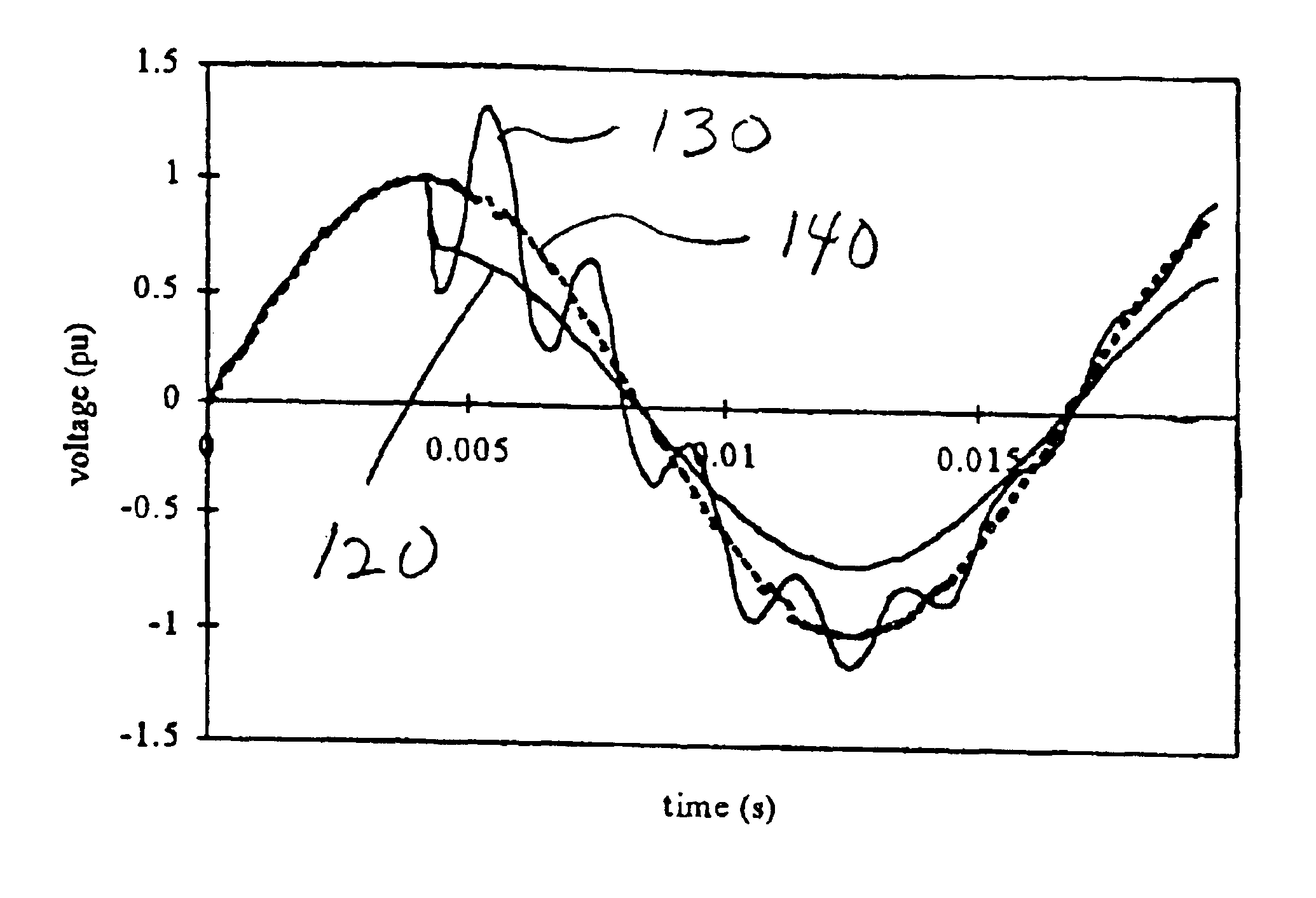
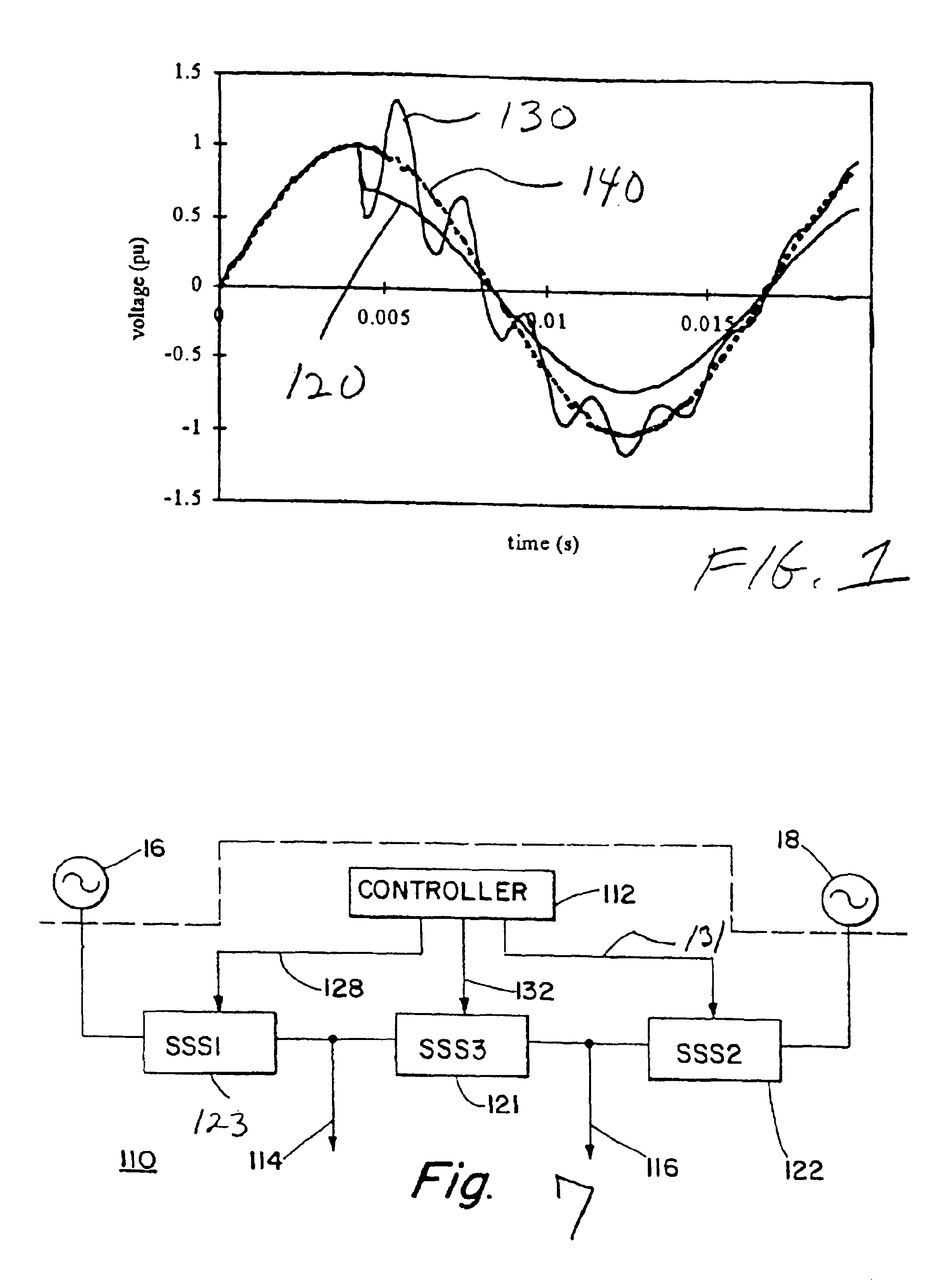
[0023]Referring now to FIG. 1, in accordance with important features of the present invention, a method and arrangement are provided for detecting and responding to voltage disturbances in an electrical power system having alternating current sources. For example, a waveform 120 of FIG. 1 represents the voltage waveform of a fault condition and a waveform 130 represents the voltage waveform where switching transients are present resulting from the switching of a capacitor bank. A waveform 140 represents the voltage waveform of a reference, i.e. an ideal waveform of an electrical power source where no voltage disturbances are present. The method and arrangement of the present invention detects the voltage disturbance represented by the fault waveform 120 while ignoring the transient response represented by the waveform 130.

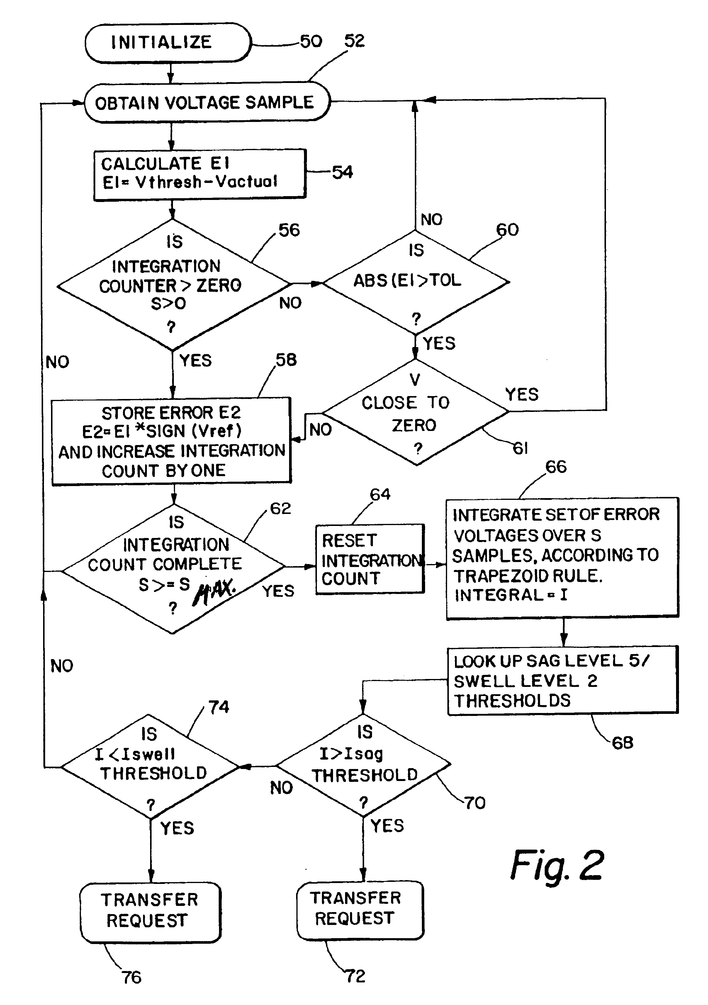
[0024]Specifically, and with reference now to FIG. 2, the method and arrangement of the present invention initiates an integration when the actual source voltage v...


PUM


Abstract

A control arrangement and method is provided for detecting and responding to disturbances in electrical power systems. In a preferred arrangement, an integration is initiated that is based on a comparison of actual voltage of a source and a reference voltage. When the integration exceeds a predetermined value, the source is considered unreliable. Also in a preferred arrangement, a determination is made as to whether or not the disturbance is a downstream fault condition. For example, this is useful for applications where a transfer is made from a first source to a second source when predetermined disturbances are detected. In this manner, the transfer of the load to a second source is avoided which would continue the supply of the downstream fault. Additionally, the arrangement distinguishes between various degrees of disturbances to permit appropriate response based on the severity and type of disturbance. For example, a first immediate response, i.e. without intentional delay, is provided for more severe disturbances while a second delayed response is provided for less severe disturbances. The control arrangements transfers the load to an alternate source of power via the use of a high-speed source-transfer switching system that both avoids undesirable current flow between sources and minimizes undesirable transfer delays.

Description

[0001]This application is a divisional application of Application No. 10 / 387,253 filed Mar. 12, 2003 now U.S. Pat. No. 6,668,232 in the names of Ennis et al. which in turn is a continuation of Application No. 09 / 556,257 filed Apr. 24, 2000 now U.S. Pat. No. 6,601,002 in the names of Ennis et al. which claimed the benefit of U.S. Provisional Application No. 60 / 131,855 filed on Apr. 29, 1999.BACKGROUND OF THE INVENTION[0002]1. Field of the Invention[0003]The present invention relates generally to methods and arrangements for detecting and responding to disturbances in electrical power systems and more particularly to methods and arrangements that detect various types of voltage disturbances while ignoring certain types of voltage disturbances and appropriately responding to the voltage disturbances.[0004]2. Description of Related Art[0005]Various types of voltage disturbances, such as sags, swells and transients, can occur on electrical power lines which are undesirable to continued p...

Claims


Application Information

Patent Timeline
Patent Type & Authority Patents(United States)
IPC IPC(8): H02J9/06H02H7/26H02H3/38H02H3/44G01R19/165H02J3/00
CPCH02H7/266H02J9/06H02H3/38H02H3/44
Inventor ENNIS, MICHAEL G.O'LEARY, RAYMOND P.RUTA, JOSEPH W.
Owner S&C ELECTRIC
Why Eureka
Try Eureka