Stapler apparatus to staple stacks of paper with different thicknesses

a stacking paper and paper staple technology, applied in the field of staplers, can solve the problems of ineffective use of staples in heavy-duty staplers to staple stacks of paper together, protruding legs affecting the person handling the stapled stacks, and only meeting the needs of a small range of staples

Inactive Publication Date: 2005-09-13
APEX MFG
View PDF4 Cites 24 Cited by
  • Summary
  • Abstract
  • Description
  • Claims
  • Application Information

AI Technical Summary

Benefits of technology

[0008]The main objective of the invention is to provide an apparatus for a stapler so that the stapler can staple stacks of paper with different thicknesses without changing staples in the stapler.
[0009]The apparatus in accordance with the present invention is installed in a conventional stapler so the stapler can staple stacks of paper with different thicknesses without having to change staples or components in the stapler. The apparatus cuts legs of a staple to a proper length after the staple has been driven completely into a stack of paper and bends the protruding ends to bind the stack of paper together. The apparatus performs these operations with a cutter, a bending template, and a cutting anvil in conjunction with a sliding bracket and a cutter actuator. Operation of the cutter is delayed by a staple driver actuator until the staple has completely penetrated the stack of paper.

Problems solved by technology

A common problem of most staplers is having correct size staples to staple a stack of paper together.
A heavy-duty stapler uses staples with long legs that are only suitable for stapling a thick stack of paper together.
Furthermore, the staples in a heavy-duty stapler cannot be used effectively to staple a thin stack of paper together, because the pointed legs of the staples for the heavy-duty stapler are so long that they wrap around and protrude from the top surface of the stack.
The protruding legs constitute a hazard to a person handling the stapled stacks.
Therefore, a stand-alone stapler that uses a specific size of staples only meets a small range of stapling needs.
Furthermore, having to have many stand-alone staplers to staple stacks of paper with different thicknesses is not economical.

Method used


Image

  • Stapler apparatus to staple stacks of paper with different thicknesses
  • Stapler apparatus to staple stacks of paper with different thicknesses
  • Stapler apparatus to staple stacks of paper with different thicknesses

Examples


Embodiment Construction

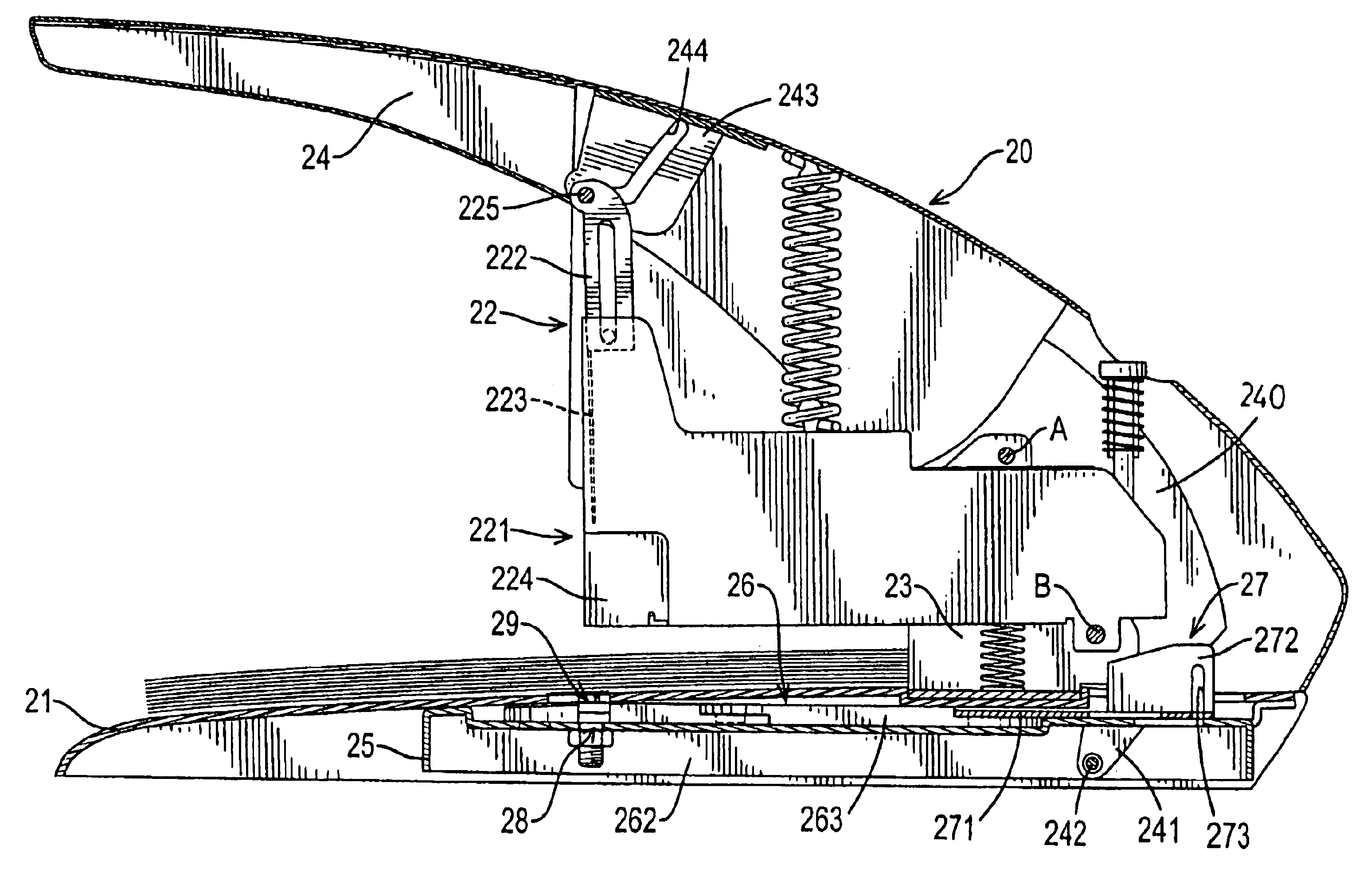
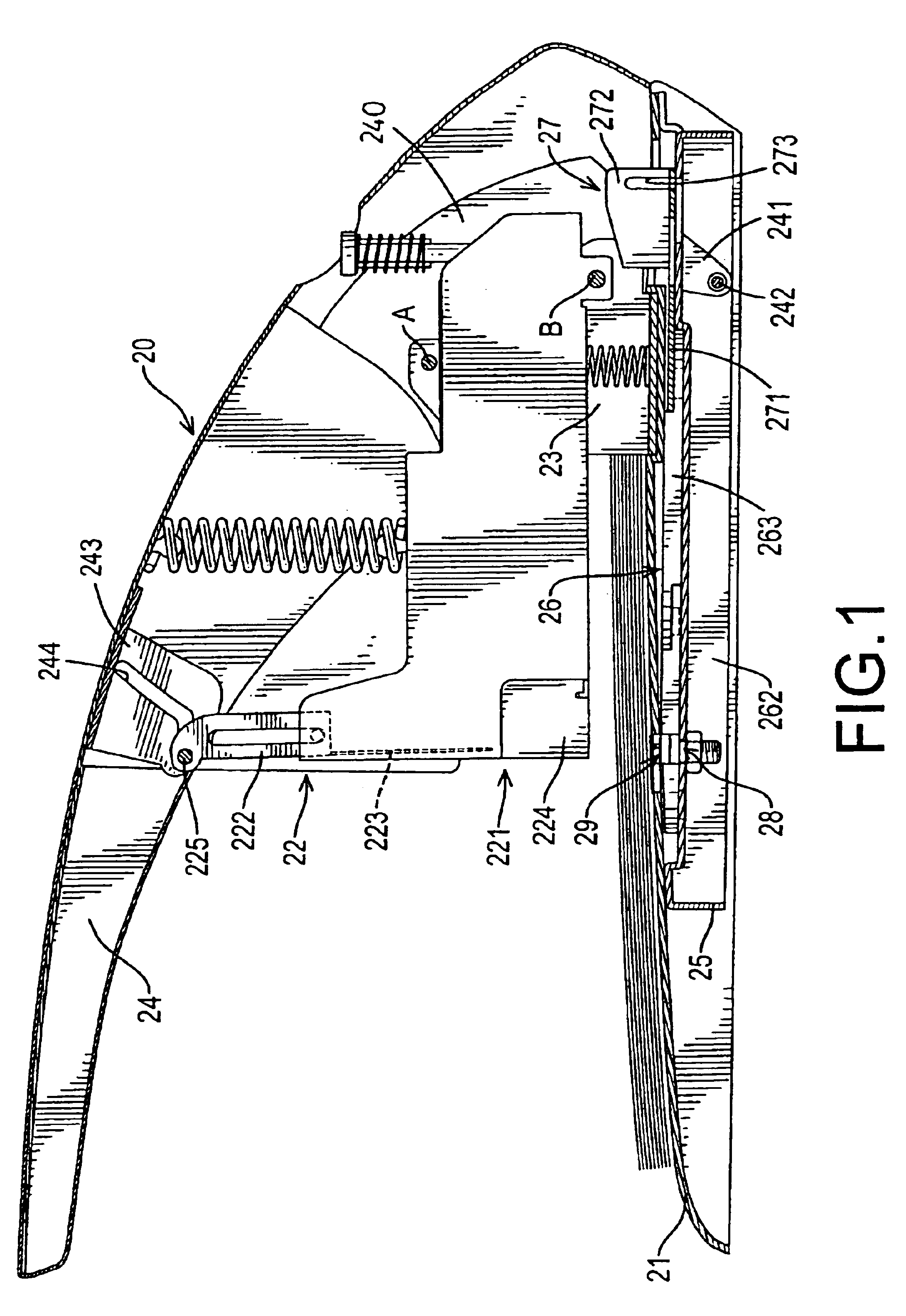
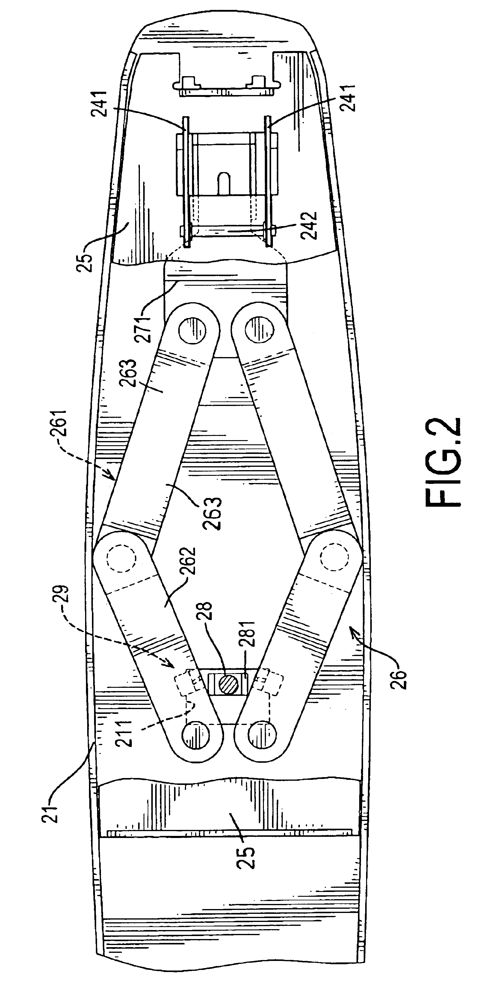
[0019]With reference to FIGS. 1 and 2, an apparatus for stapling stacks of paper with different thicknesses in accordance with the present invention is mounted in a conventional stapler (20). The stapler (20) comprises a base (21), a stapling mechanism (22), a mounting bracket (23) and a lever (24). The base (21) is hollow and has a top (not numbered), a cavity (not numbered) and a staple opening (211). The staple opening (211) is defined through the top and communicates with the cavity.

[0020]The mounting bracket (23) is substantially U-shaped, is attached to the top of the base (21) and has a magazine pivot point (B) and a lever pivot point (A). The lever pivot point (A) is formed above the magazine pivot point (B).

[0021]The stapling mechanism (22) is attached pivotally to the mounting bracket (23) at the magazine pivot joint (B) and comprises a magazine assembly (221), a staple driver guide (222), a staple driver (223) and a staple driver actuator (243).

[0022]The magazine assembly...


PUM


Abstract

A staple apparatus is installed in a stapler so the stapler can staple stacks of paper with different thicknesses without having to change staples or components in the stapler. The apparatus cuts legs of a staple to a proper length after the staple has been driven completely into a stack of paper and bends the protruding ends to bind the stack of paper together. The apparatus performs these operations with a cutter, a bending template, and a cutting anvil in conjunction with a sliding bracket and a cutter actuator. Operation of the cutter is delayed by a staple driver actuator until the staple has completely penetrated the stack of paper.

Description

BACKGROUND OF THE INVENTION[0001]1. Field of the Invention[0002]The present invention relates to a stapler, and more particularly to a stapler that has an apparatus to staple stacks of paper with different thicknesses without changing staples in the stapler.[0003]2. Description of Related Art[0004]Staplers use staples that are typically U-shaped and have two pointed legs to fasten pieces of paper together. The pointed legs of a staple are forced through the pieces of the paper, extend out of the pieces of paper and are bent to hold the pieces of paper together.[0005]A common problem of most staplers is having correct size staples to staple a stack of paper together. A heavy-duty stapler uses staples with long legs that are only suitable for stapling a thick stack of paper together. Furthermore, the staples in a heavy-duty stapler cannot be used effectively to staple a thin stack of paper together, because the pointed legs of the staples for the heavy-duty stapler are so long that th...

Claims


Application Information

Patent Timeline
Patent Type & Authority Patents(United States)
IPC IPC(8): B25C5/00B25C5/06B25C5/02B25C5/08
CPCB25C5/08
Inventor TSAI, ERIC
Owner APEX MFG
Why Eureka
Try Eureka