Toilets with trapways having an air dam

a technology of air dam and toilets, which is applied in water installations, water closets, constructions, etc., can solve the problems of slow flushing, insufficient reduction or elimination of “blow back” in prior art designs, and slow flushing, so as to reduce or eliminate the formation of air pockets, reduce water waste, and quick fill key portions

Inactive Publication Date: 2005-09-20
KOHLER CO
View PDF11 Cites 5 Cited by
  • Summary
  • Abstract
  • Description
  • Claims
  • Application Information

AI Technical Summary

Benefits of technology

[0015]The present invention thus provides a toilet with a unique trapway design that has several advantages over the prior art. The trapway is designed so that water from the bowl completely and quickly fills key portions of the trapway during a flush cycle. This leads to rapid evacuation of the bowl contents, minimizing water waste.
[0016]The rearwardly slightly canted down leg reduces or eliminates the formation of air pockets in the water dam region which would otherwise interfere with the siphoning effect of the trapway. The uniform circular cross-section of the curved water dam region helps to lift the surface of the fluid at the water dam during siphon initiation, which further helps to remove air.
[0017]Most importantly, the air dam aids in rapid flushing by separating the fluid from the inside wall of the down leg thereby creating a sheet of fluid that blocks air blow back from flowing into the low-pressure region downstream from the air dam.

Problems solved by technology

One common problem is to try to achieve this in low volume toilets.
In this regard, for environmental and water conservation reasons many jurisdictions now restrict the sales of toilets which use too much water per flush.
However, prior art designs often did not adequately reduce or eliminate “blow back”, which is a reverse flow of air from the plumbing lines into a low pressure region of the trapway.
To some extent, this obstructed flow through the trapway and caused a slower flush.

Method used


Image

  • Toilets with trapways having an air dam
  • Toilets with trapways having an air dam
  • Toilets with trapways having an air dam

Examples


Embodiment Construction

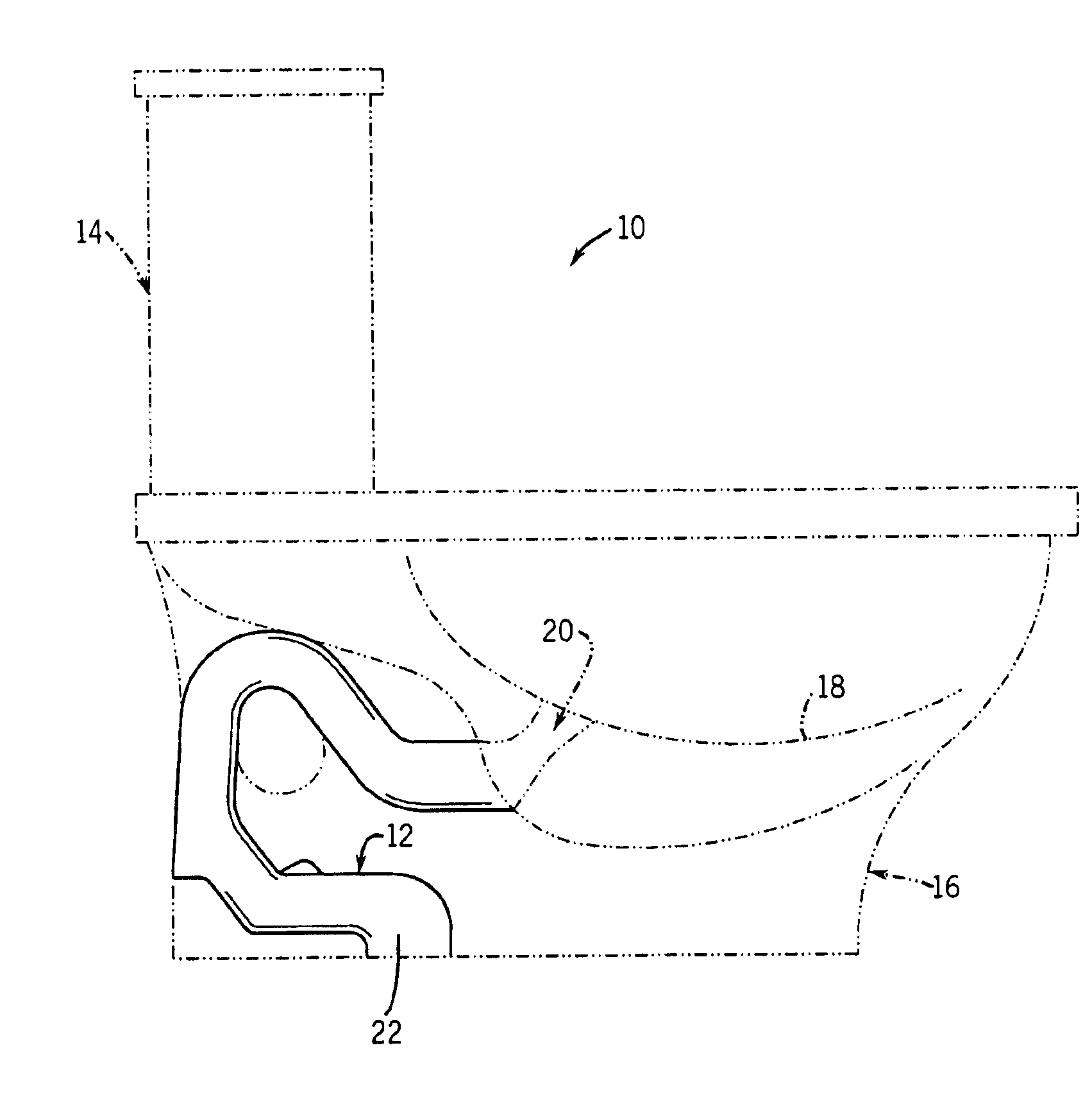
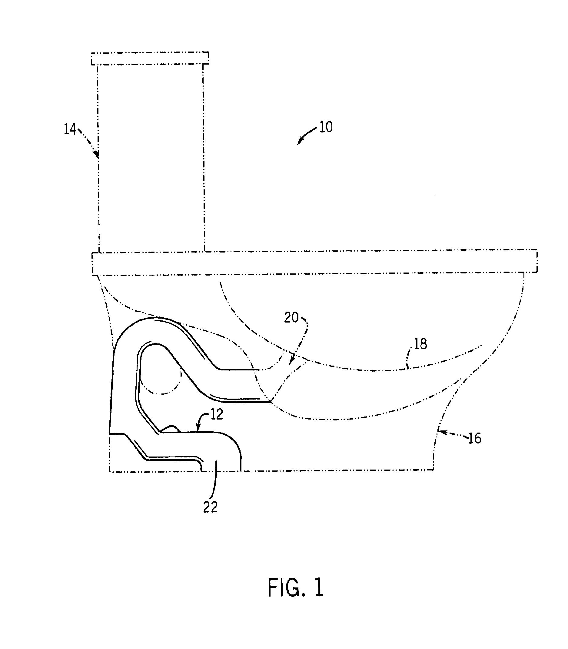
[0029]FIG. 1 illustrates a toilet 10 having a siphon passage or trapway 12 design according to the present invention. In particular, other than the trapway 12, the toilet 10 can be any suitable one or two piece toilet, preferably of a low volume flush design, as known in the art.

[0030]For example, FIG. 1 shows in hidden lines a two-piece toilet having a separate flush tank 14 mounted to a bowl base 16. A hole (not shown) in the bottom of the flush tank 14 aligns with a hole (not shown) in the top of the bowl base 16 to allow water to pass from the flush tank and into the a bowl 18, formed in the bowl base 16, during a flush cycle.

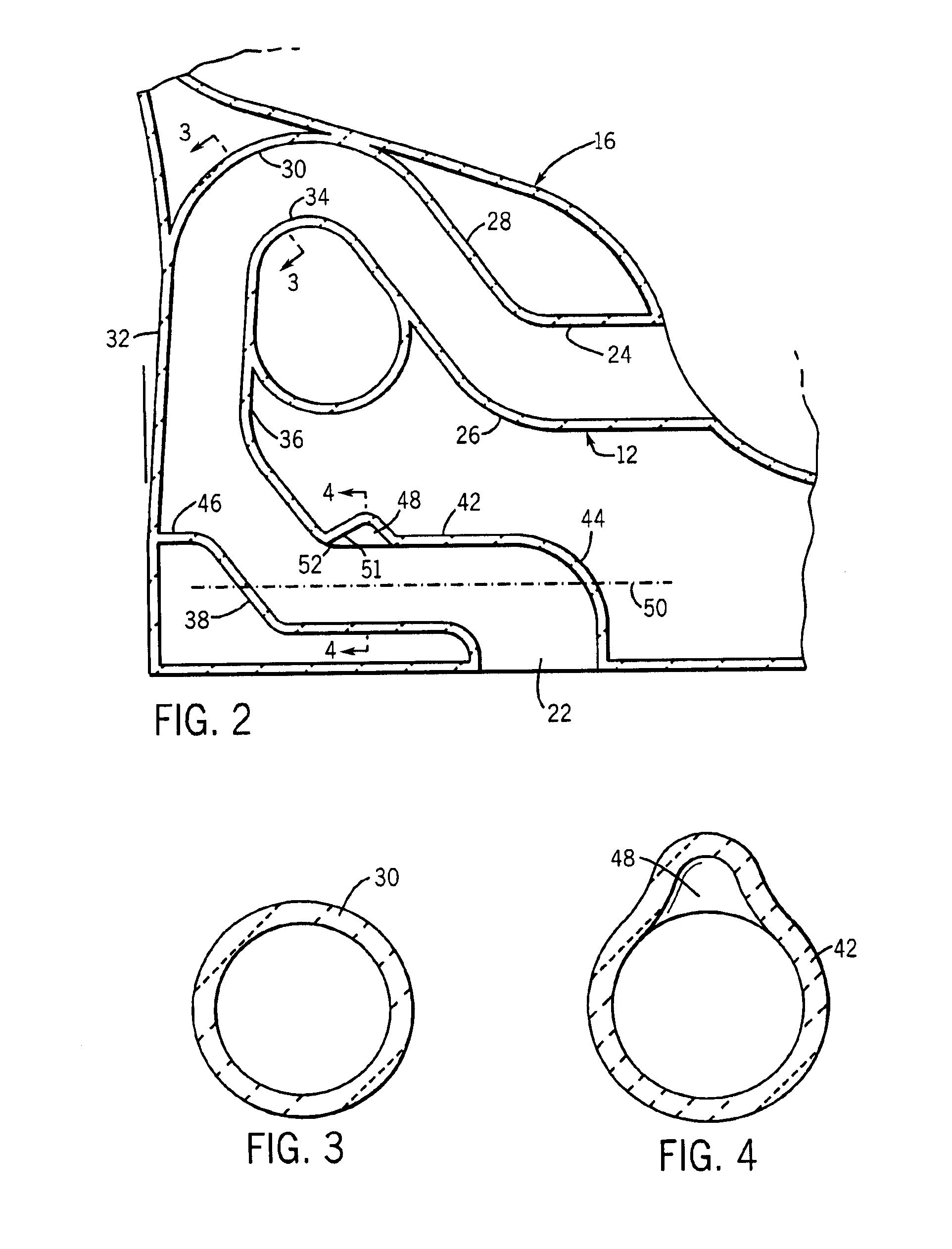
[0031]The trapway 12 extends from an opening 20 in the bowl 18 along a serpentine path, having an essentially uniform and constant circular cross-section (as shown in FIG. 3) at least in the second bend 30 at the water dam 34. The trapway has an outlet opening 22 at the bottom of the bowl base 16, which mounts over the open end of a waste plumbing line (not...


PUM


Abstract

A toilet has a trapway extending between a bowl opening and an outlet opening. The trapway defines a curved water dam region above the bowl opening, a down leg, and a straight out leg between the down leg and the outlet opening. The out leg has an air dam cavity such that the trapway has an increased cross-sectional area at the air dam.

Description

CROSS-REFERENCE TO RELATED APPLICATION[0001]Not applicable.STATEMENT OF FEDERALLY SPONSORED RESEARCH OR DEVELOPMENT[0002]Not applicable.BACKGROUND OF THE INVENTION[0003]The present invention relates to plumbing fixtures, and in particular to toilets provided with improved trapways.[0004]Conventional toilets have a bowl and a flush tank cast in one or two pieces. A serpentine passage is formed in the toilet (or the bowl component of a two-piece toilet) to transport the contents of the bowl to an outlet opening that is usually at the bottom of the bowl. That opening is coupled to the waste plumbing lines of the building.[0005]This passage is generally referred to as the bowl “siphon” or “trapway”. An upstream portion of this passage is normally filled with water, before and after a flush cycle, to “trap” sewer gases downstream thereof so as to prevent them entering the building interior. Water is maintained in the bowl and the upstream part of the trapway by forming an arched section ...

Claims


Application Information

Patent Timeline
Patent Type & Authority Patents(United States)
IPC IPC(8): E03D11/02
CPCE03D11/08E03D11/02
Inventor KURU, WILLIAM C.MUKERJI, SUDIP
Owner KOHLER CO
Why Eureka
Try Eureka