Zipper head structure

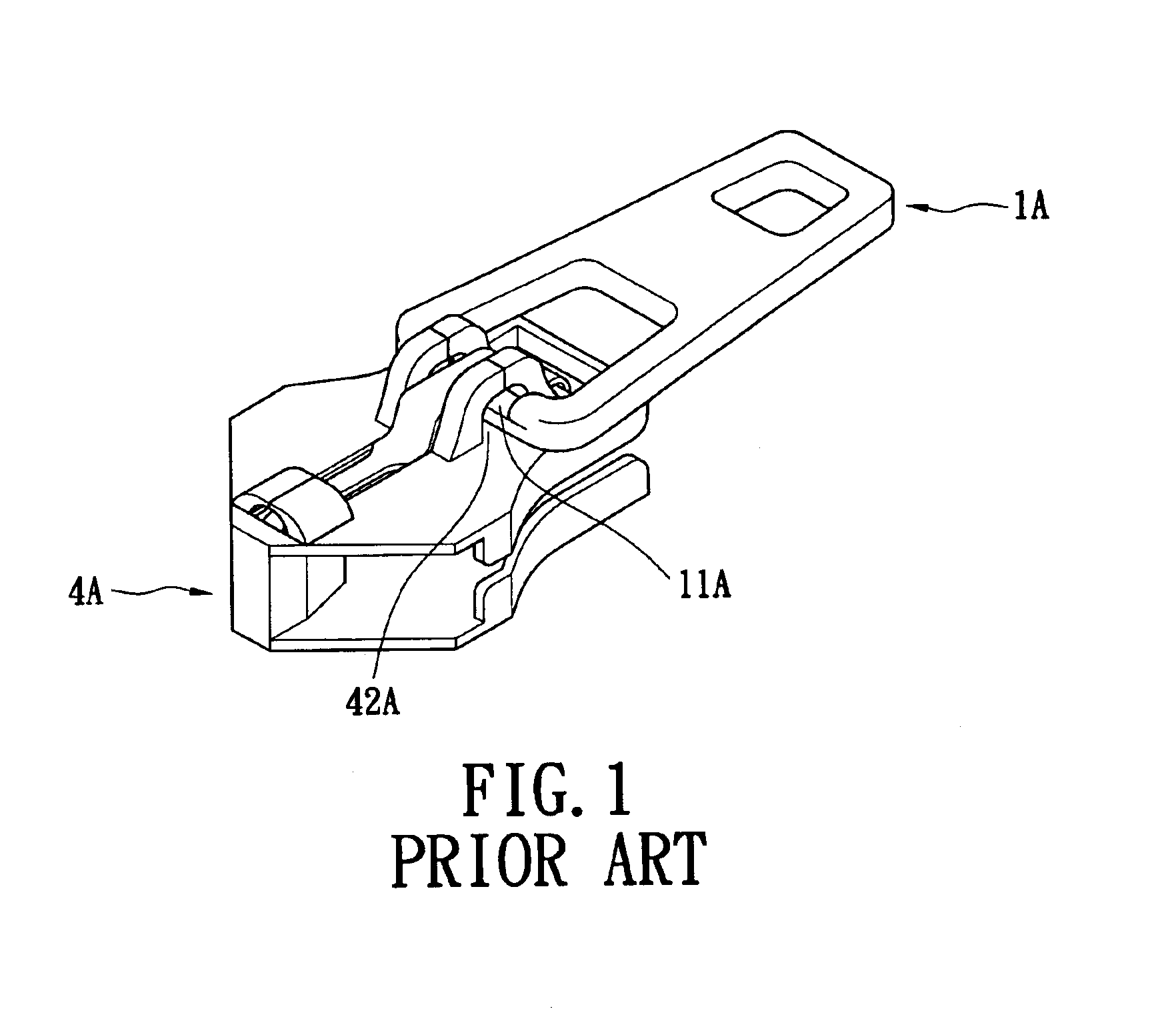
a zipper head and head technology, applied in the direction of snap fasteners, slide fasteners, press-button fasteners, etc., can solve the problems of inconvenience and drawbacks of practical use the inability to dully pull the tag b>1/b>a dully, and the inability to bear the torque of the above conventional zipper head, etc., to achieve labor-saving, labor-saving and uniform effort points , the effect of larg

Inactive Publication Date: 2005-09-20
WANG LIEN CHOU
View PDF20 Cites 2 Cited by
  • Summary
  • Abstract
  • Description
  • Claims
  • Application Information

AI Technical Summary

Benefits of technology

[0005]The primary object of the present invention is to provide a zipper head structure to improve the conventional zipper head whose pull tag can only be pulled forwards and backwards or leftwards and rightwards, and swings loosely. The pull tag of the zipper head of the present invention can rotate for 360 degrees in a slipshod way to match the motion of a zipper for providing the most appropriate and labor-saving angle. Moreover, a uniform effort point and a large effort area are accomplished, hence providing a convenient, labor-saving zipper head structure with a large torque.

Problems solved by technology

However, the pull tag 1A of the above conventional zipper head can only be dully pulled forwards and backwards.
Therefore, the bearable torque thereof is relatively limited.
Accordingly, the above conventional zipper head has inconvenience and drawbacks in practical use.

Method used


Image

  • Zipper head structure
  • Zipper head structure
  • Zipper head structure

Examples


Embodiment Construction

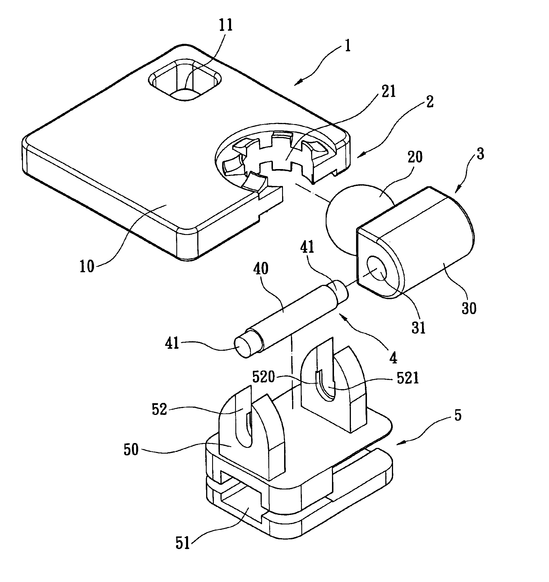
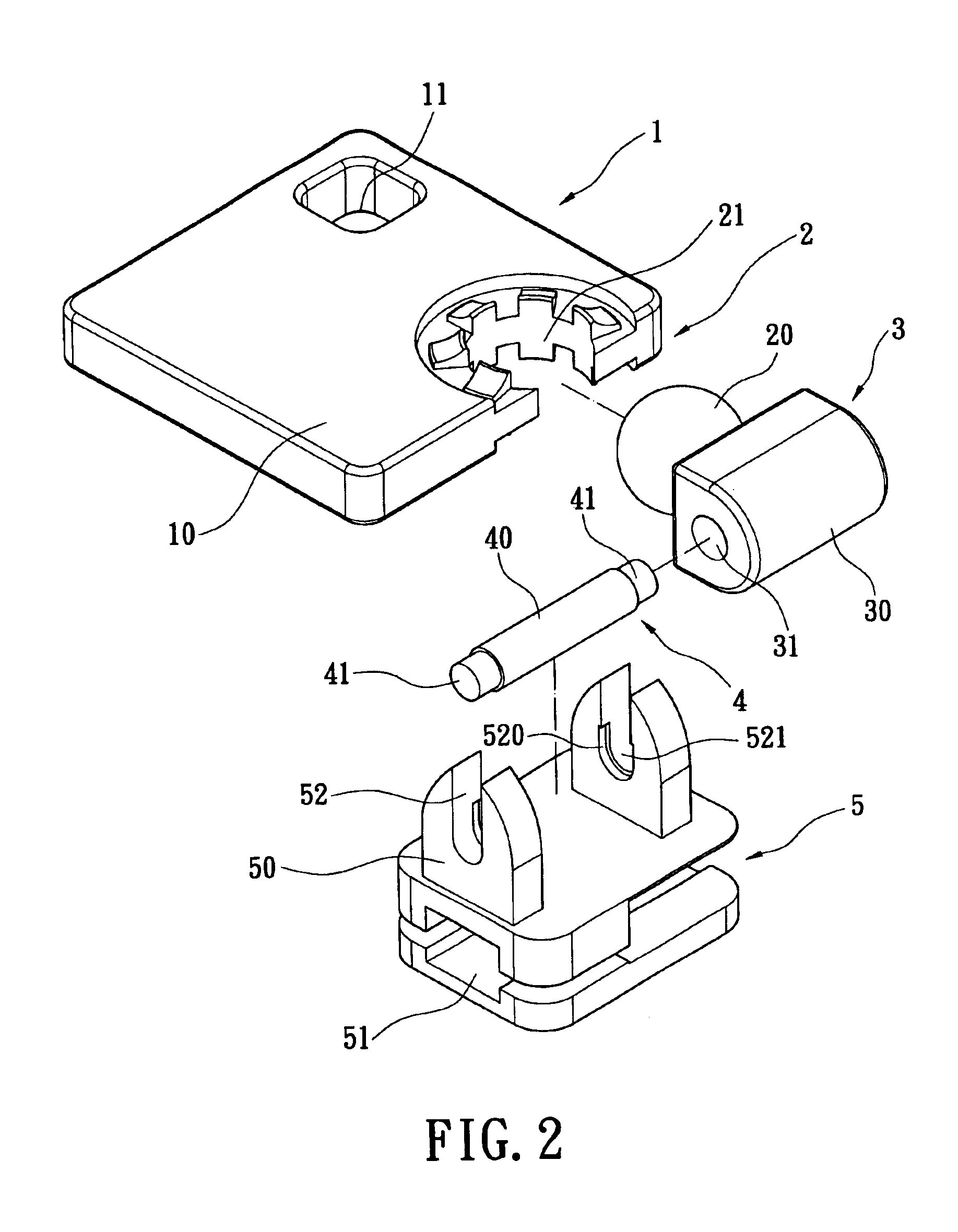
[0017]As shown in FIGS. 2 and 3, the present invention provides a zipper head structure comprising a pull tag 1, a universal joint 2, an axis 3, a central pin 4 and a base 5. The pull tag 1 has a plank 10 with a small hole 11 formed at an edge or corner thereof for convenient hanging of a decoration or a nameplate on the pull tag 1. The plank 10 can be square, rectangular or circular. The shape of the plank 10 is not limited, and can vary according to necessity.

[0018]The universal joint 2 comprises a ball body 20 and an arc tooth base 21. The arc tooth base 21 is arranged at an edge of the pull tag 1. The arc tooth base is one larger than a semicircle.

[0019]The axis 3 has a cylinder 30. The ball body 20 is integrally arranged outside the cylinder 30 of the axis 3. The arc tooth base 21 is engaged with the ball body 20 to tightly connect the pull tag 1 and the axis 3. The ball body 20 is rotatably arranged in the arc tooth base 21. The universal joint 2 can let the pull tag 1 can fre...


PUM


Abstract

A zipper head structure comprises a pull tab, a base and a universal joint. The base has a receiving space for receiving a zipper chain scoop. The universal joint is connected between the pull tab and the base. Through the design of the universal joint, the pull tab can rotate for 360 degrees to match the motion of the zipper, hence providing the most appropriate and labor-saving angle.

Description

FIELD OF THE INVENTION[0001]The present invention relates to a zipper head structure and, more particularly, to a zipper head whose pull tab can rotate for 360 degrees and achieve a large torque.BACKGROUND OF THE INVENTION[0002]As shown in FIG. 1, a conventional zipper head comprises a pull tag 1A and a base 4A. A pivotal portion 11A is disposed at one end of the pull tag 1A. A pivotal groove 42A is disposed at the upper half of the base 4A. The pivotal portion 1A of the pull tag 1A is pivotally placed in the pivotal groove 42A of the base 4A for connecting the pull tag 1A and the base 4A.[0003]However, the pull tag 1A of the above conventional zipper head can only be dully pulled forwards and backwards. In order that the pull tag 1A can be easily pulled forwards and backwards, the connection between the pull tag 1A and the base 4A cannot be too tight in design. Therefore, the bearable torque thereof is relatively limited.[0004]Accordingly, the above conventional zipper head has inc...

Claims


Application Information

Patent Timeline
Patent Type & Authority Patents(United States)
IPC IPC(8): A44B19/24A44B19/26
CPCA44B19/262Y10T24/2586
Inventor WANG, LIEN CHOU
Owner WANG LIEN CHOU
Why Eureka
Try Eureka