Heat dissipating device with uniform heat points

a heat dissipating device and heat dissipation technology, which is applied in the direction of indirect heat exchangers, lighting and heating apparatus, and semiconductor/solid-state device details, etc., can solve the problems of heat pipe contact with heat generating sources, heat is too concentrated to be dissipated, and achieve uniform heat points , improve heat dissipation performance, increase the effect of effective heat dissipation area

Inactive Publication Date: 2006-04-04
CPUMATE INC
View PDF9 Cites 53 Cited by
  • Summary
  • Abstract
  • Description
  • Claims
  • Application Information

AI Technical Summary

Benefits of technology

[0004]The present invention provides a heat dissipating device with uniform heat points. By rearrange the positions of the heat pipes, heat points are distributed on the heat generating source. Therefore, the effective heat dissipation areas are increased to provide improved heat dissipation performance.
[0005]The heat dissipating device provided by the present invention comprises a first heat sink, a second heat sink aligned over the first heat sink, and at least two heat pipes. Each of the heat pipes includes a heat absorbing portion in thermal communication with the first heat sink and a heat dissipating portion in thermal communication with the second heat sink. The distance between the heat absorbing portions of the heat pipes is smaller than the distance between the heat generating portions of the heat pipes, such that the heat generated by a heat source can be effectively absorbed, and efficiently and uniformly dissipated by the heat dissipation portions distributed over a large area of the second heat sink.

Problems solved by technology

Therefore, if the distance between the neighboring heat pipes is too large, it is disadvantageous for the heat pipe to be in contact with the heat generating source.
On the contrary, if the distance between the neighboring heat pipes is too small, the heat is too concentrated to be dissipated.

Method used


Image

  • Heat dissipating device with uniform heat points
  • Heat dissipating device with uniform heat points
  • Heat dissipating device with uniform heat points

Examples


Embodiment Construction

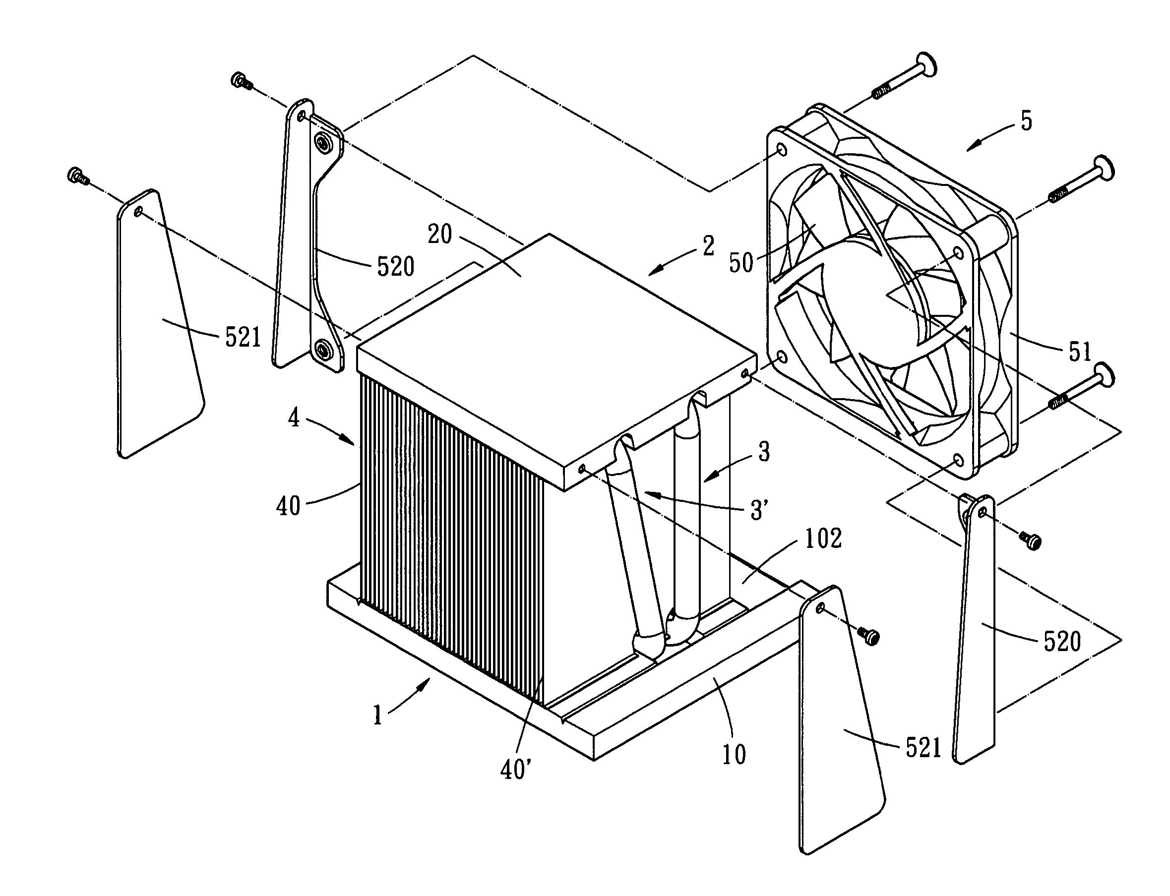
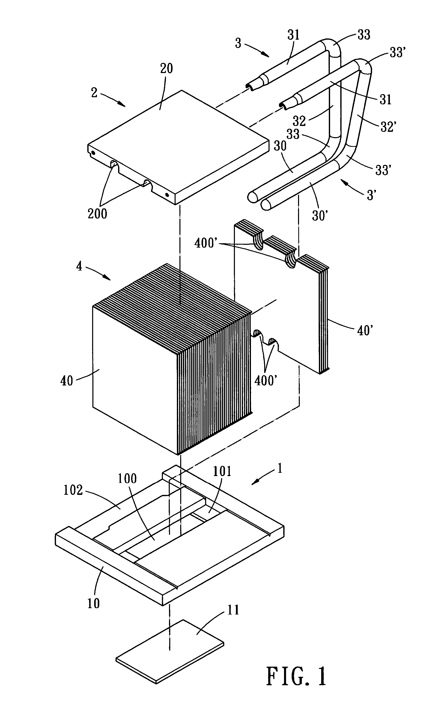
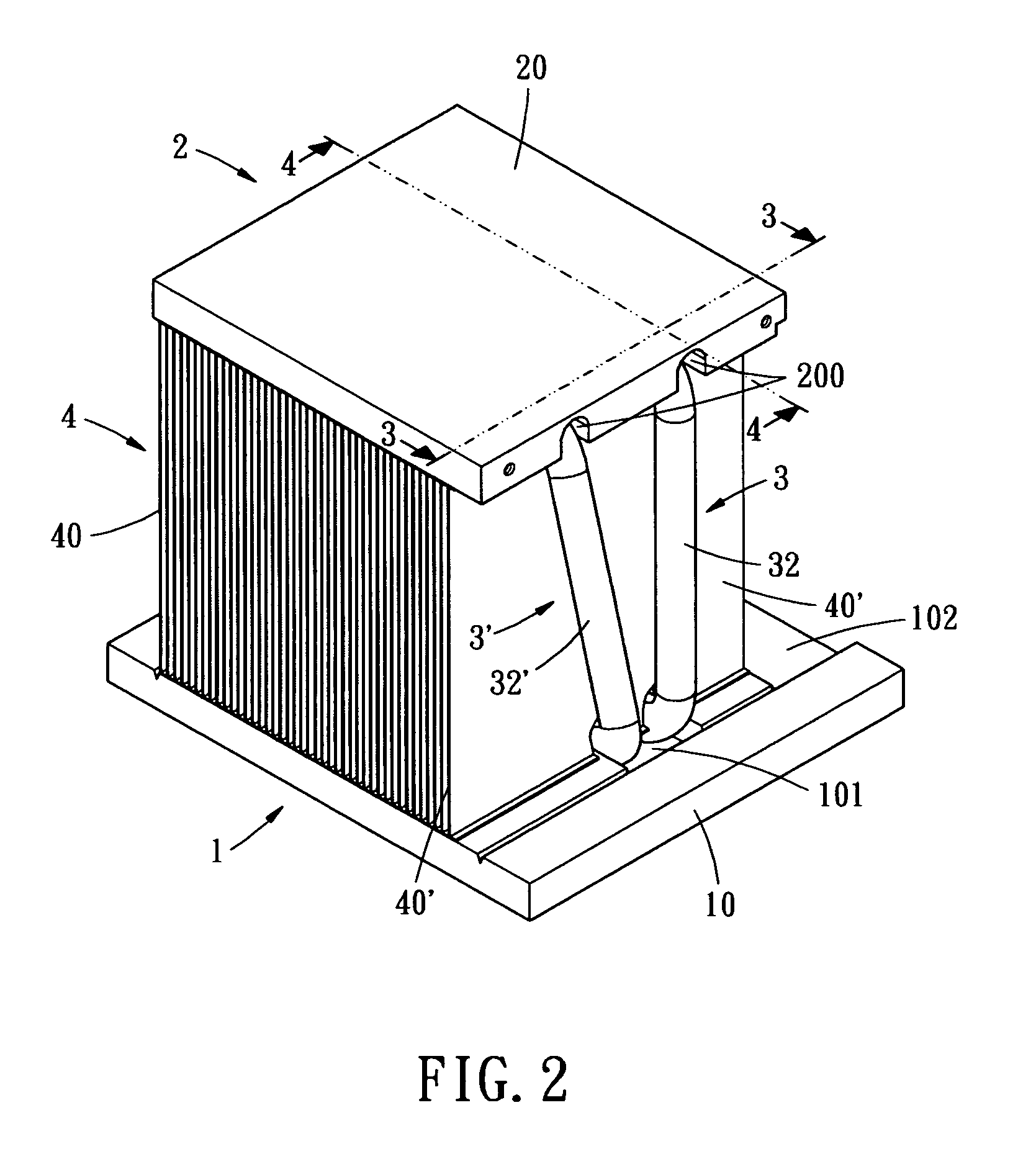
[0014]FIGS. 1–3 depict an exploded view, a perspective view and a cross-sectional view of a heat dissipating device with uniform heat points. As shown, the heat dissipating device includes a first heat sink 1, a second heat sink 2 and at least two heat pipes 3 and 3′.

[0015]The heat sink 1 is fabricated from good thermal conductive material such as aluminum. In this embodiment, the heat sink 1 has a planar configuration. The heat sink includes a substrate 10. The bottom surface of the substrate 100 is recessed with a receiving slot 100 for embedding a thermal conductor 111 therein. The thermal conductor 11 has a thermal coefficient larger than that of the first heat sink 1. The thermal conductor 11 can be fabricated from copper, for example. The thermal conductor 11 has a planar configuration to be directly attaching to a heat generating device such as a central processing unit (CPU) or an electronic device. The top surface of the substrate 10 is opened with a slot 101 aligned over a...


PUM


Abstract

A heat dissipating device with uniform heat points, having a first heat sink, a second heat sink and at least two heat pipes. The second heat sink is aligned over the first heat sink. Each heat pipe has a heat absorbing portion and a heat dissipating portion. The heat absorbing and dissipating portions of each heat pipe are in thermal communication with the first and second heat sinks, respectively. The distance between two neighboring heat absorbing portions is smaller than the distance between the heat pipe and the heat sink. Thereby, the heat absorbing portions are concentrated to absorb heat generated by a heat source, and the heat dissipating portions are distributed over a larger area to effectively dissipate the heat.

Description

BACKGROUND OF THE INVENTION[0001]The present invention relates to a heat dissipating device with uniform heat points, and more particular, to a heat dissipating device of which the heat pipes are rearranged.[0002]Heat pipes have been broadly applied to dissipate heat generated by electronic devices for having the characteristics of high thermal conductivity, light weight, simple structure and capability of transfer large amount of heat without consuming electricity.[0003]To apply the heat pipes to heat dissipating devices of electronic products, one ends of the heat pipes are typically in thermal communication with the heat generating devices of the electronic products, while the other ends of the heat pipes include a plurality of fins. By the high thermal conductivity of the heat pipes, the heat generated by the heat generating devices are transferred to the fins instantly to reduce the temperature of the heat generating devices. Meanwhile, the heat accumulated in the fins can be d...

Claims


Application Information

Patent Timeline
Patent Type & Authority Patents(United States)
IPC IPC(8): H05K7/20F28D15/00H01L23/427
CPCH01L23/427H01L2924/0002H01L2924/00F28D15/0275
Inventor LIN, KUO-LENTSUI, HUI-MIN
Owner CPUMATE INC
Why Eureka
Try Eureka