Gutter shield

a technology of shields and shields, applied in the field of shields, can solve the problems of many of these guards not working as desired, and the concept will not necessarily work,

Inactive Publication Date: 2005-09-20
BROCHU GUY
View PDF5 Cites 38 Cited by
  • Summary
  • Abstract
  • Description
  • Claims
  • Application Information

AI Technical Summary

Benefits of technology

[0014]As will be appreciated, during a period of heavy rain or the like, the drainage may not be instantaneous and acc...

Problems solved by technology

However, many of these guards do not function as desired and access must still be had to the eaves trough for cleaning purposes.
However, this concept will ...

Method used


Image

  • Gutter shield
  • Gutter shield
  • Gutter shield

Examples


Embodiment Construction

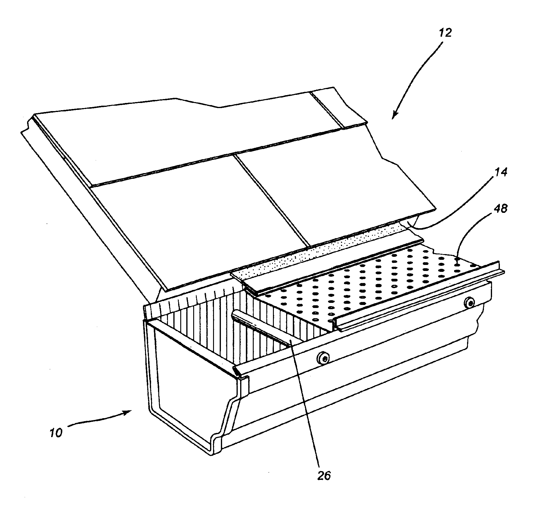
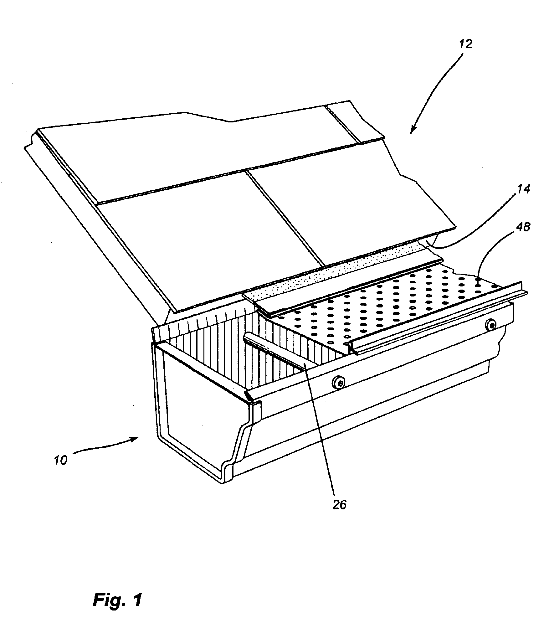
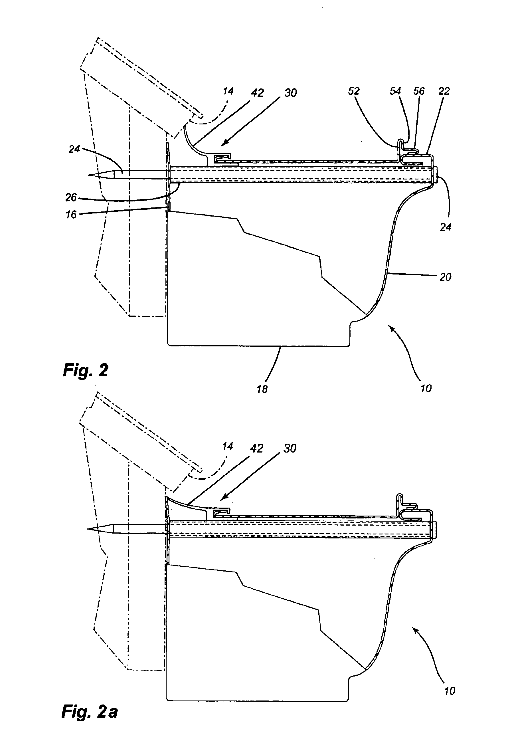
[0022]Referring to the drawings in greater detail and by reference characters thereto, it is illustrated a gutter generally designated by reference numeral 10 and which is attached to a roof generally designated by reference numeral 12. As is conventional, there is provided a drip edge 14 extending from under the edge of the roof.

[0023]Gutter 10 is a conventional gutter and includes a back wall 16 lying substantially adjacent to the facia of the structure. Extending between a front wall 20 and back wall 16 is a bottom 18. Front wall 20 includes a front top wall 22 which extends horizontally inwardly and which is folded under to present a finished edge as is conventional. Gutter 10 is secured by means of nails 24 which pass through an internal shroud 26, again as is well known in the art.

[0024]The device of the present invention includes a mounting member generally designated by reference numeral 30 and which will now be referred to. Mounting member 30 has a base 32 which extends thr...


PUM


Abstract

A gutter shield for protecting a gutter from the gutter shield having a mounting member secured to the gutter, a guard member with an elongated configuration and having a plurality of apertures extending therethrough to permit water drainage into the gutter, the mounting member also having a flexible sealing element extending outwardly therefrom, the flexible ceiling element being designed to seal against either the side of the gutter or a structural element. The device is suitable for many different sizes of gutters.

Description

[0001]The present application is a continuation-in-part of application Ser. No. 10 / 017,330 filed Dec. 14, 2001 now abandoned.FIELD OF THE INVENTION[0002]The present invention relates to a shield for a rainwater gutter assembly or a eaves trough.BACKGROUND OF THE INVENTION[0003]The use of shields for gutters or eaves troughs is well known in the prior art and there have been many proposals for different types of shields. The purpose of the shield is essentially to permit passage of rainwater from the roof to the eaves trough while protecting the same from extraneous foreign matter such as leaves and the like.[0004]To date, there have been several different approaches taken. A first approach is utilizing a shield or a guard which is apertured and permits the passage of rainwater while ostensibly barring the passage of extraneous material. However, many of these guards do not function as desired and access must still be had to the eaves trough for cleaning purposes. Also, each one must...

Claims


Application Information

Patent Timeline
IPC IPC(8): E04D13/04E04D13/076
CPCE04D13/076
Inventor BROCHU, STEPHANE
Owner BROCHU GUY
Why Eureka
Try Eureka