
Surgical hand support

a hand support and hand technology, applied in the field of surgical hand support, can solve the problems of inability to hold all the necessary objects (thumb and retractors) with the available number of hands, difficulty in maintaining the thumb in a position that allows appropriate access and visualization of the volar area, and inability to reach for the hand to the surgical instruments needed for the operation,

Active Publication Date: 2005-09-20
MENGATO RICHARD A
View PDF9 Cites 11 Cited by
  • Summary
  • Abstract
  • Description
  • Claims
  • Application Information

AI Technical Summary

Problems solved by technology

For many surgical procedures on the thumb, however, this natural position of the thumb relative to the hand makes it difficult to maintain the thumb in a position that allows appropriate access and visualization of the areas of interest on the volar side of the thumb by simple positioning of the hand in the usual manner, i.e., with the hand lying flat with the palm facing upward.
If limited assistance is available, such as is the situation with a surgical case being done by a single surgeon with a single scrub technician or scrub nurse assisting, holding all of the necessary objects (thumb and retractors) can be extremely awkward, cumbersome or impossible with the available number of hands.
If the scrub assistant has one or both hands involved holding the thumb and hand, he or she may not be able to hold necessary retractors or reach for and hand to the surgeon instruments needed to perform the operation.
For procedures being done under magnification, particularly under an operating microscope, manually holding the thumb may cause an unacceptable amount of shaking for repairing a nerve or artery even with a steady handed assistant.
This can make the procedures more difficult and more time consuming.
In addition, the very expensive rate for the operating room in this instance can cause significant cost increases for such surgical procedures.

Method used


Image

  • Surgical hand support
  • Surgical hand support
  • Surgical hand support

Examples


Embodiment Construction

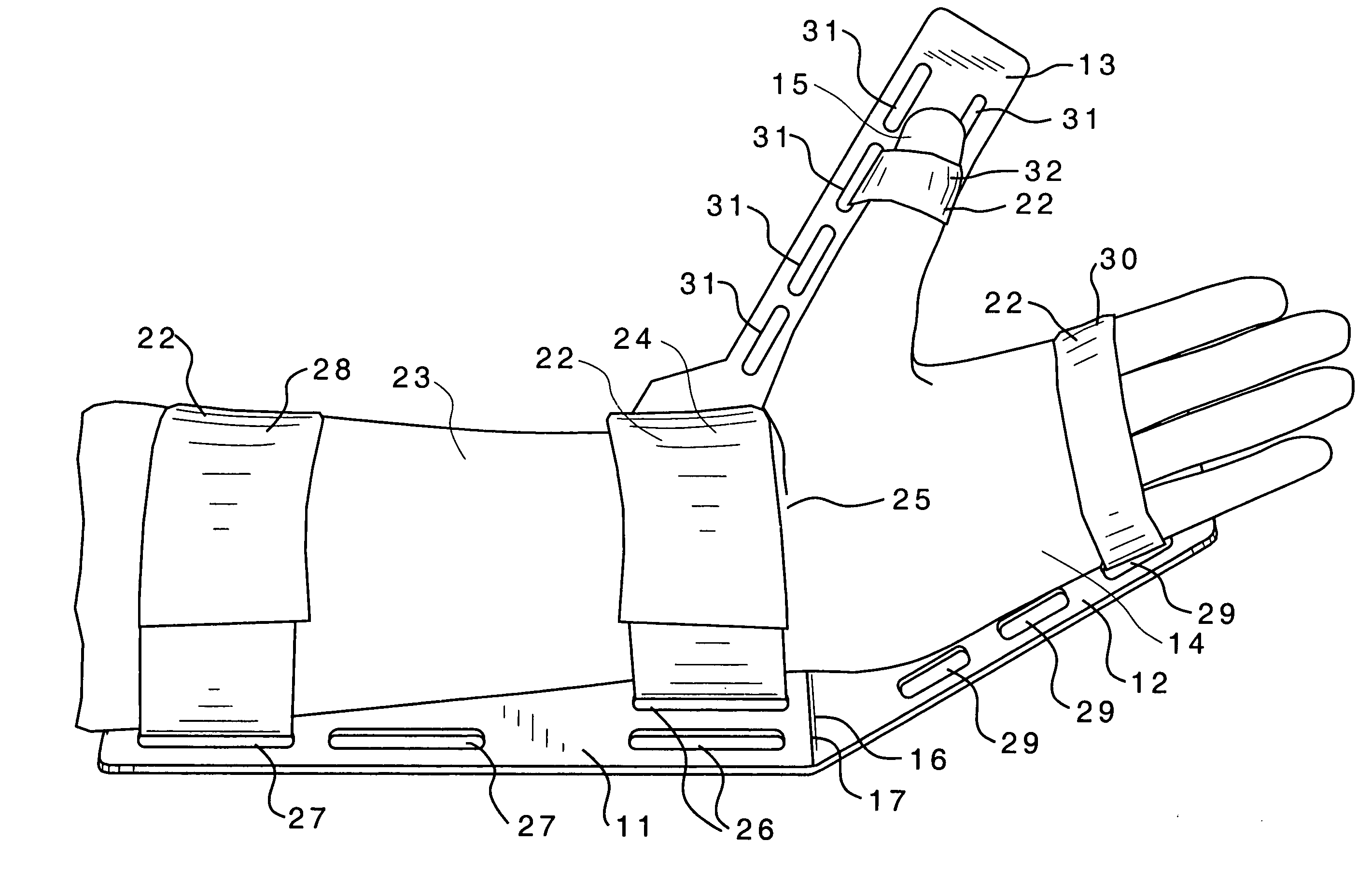
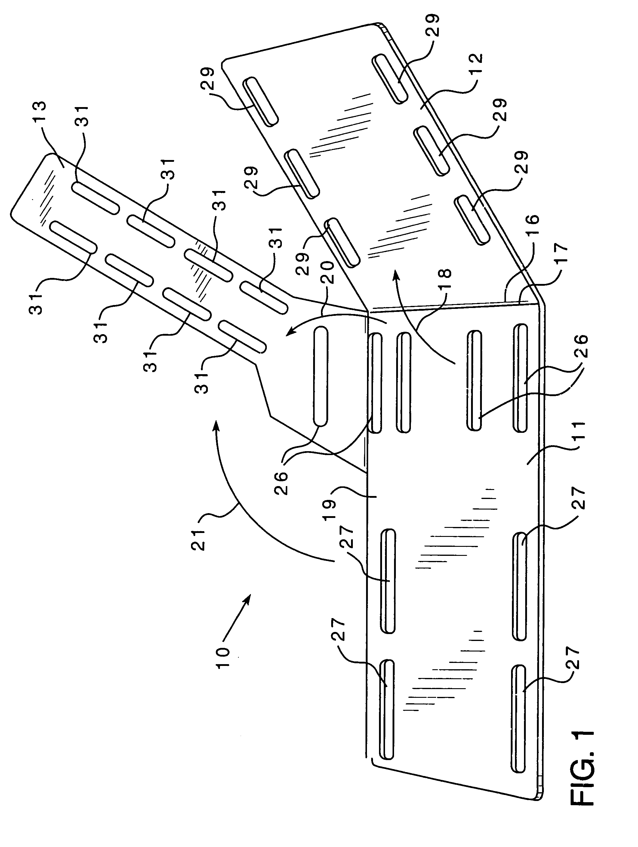
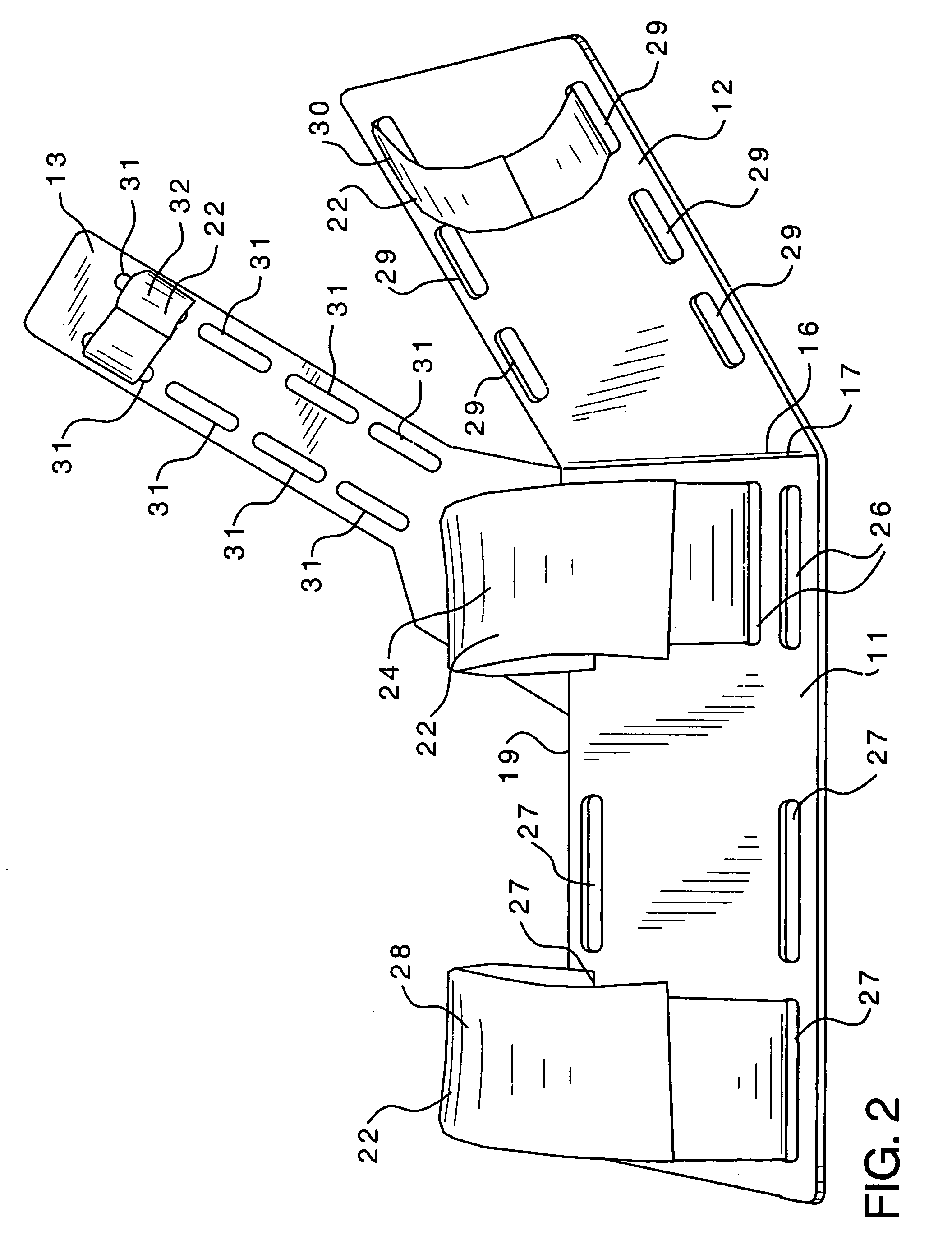
[0013]Referring to the drawings, the surgical hand support 10 of the present invention is rigid and may be constructed of any suitable rigid material such as stainless steel or plastic which can be easily cleaned and sterilized. The rigid support 10 includes an elongate forearm support plate 11 with a hand support plate 12 and a thumb support plate 13 extending from support plate 11. Hand support plate 12 and thumb support plate 13 are respectively dimensioned for engaging the back of an individual's hand 14 and the thumb 15 of the hand 14 as is illustrated in FIG. 3.

[0014]The hand support plate 12 extends upwardly from a wrist bend 16 on the forward edge 17 of forearm support plate 11 at an obtuse angle 18, which in this instance is approximately 135°. Thumb support plate 13 extends upwardly from the side edge 19 of forearm support plate 11 adjacent wrist bend 16 at an obtuse angle 20, which in this instance is approximately 120°. Thus the wrist is held in a position of volar flexi...


PUM


Abstract

A surgical hand support for performing surgical procedures on the volar side of the human thumb. The support includes an elongate forearm support plate with a hand support plate and a thumb support plate extending from this forearm support plate. The hand support plate and thumb support plate are dimensioned for respectively engaging the back of an individual's hand and thumb. The hand support plate extends upwardly from a wrist bend on the forward edge of the forearm support plate at an obtuse angle. The thumb support plate extends upwardly from a side edge of the forearm plate adjacent the wrist bend at an obtuse angle and the thumb support plate also extends forward from the side edge of the forearm plate at an obtuse angle and adjustable straps are provided for securing the forearm to the forearm plate, the hand to the hand plate and the thumb to the thumb plate whereby the volar side of the thumb is suitably presented for surgery.

Description

BACKGROUND OF THE INVENTION[0001]This invention relates generally to medical devices, and more particularly to a surgical hand support for performing surgical procedures on the volar side of the human thumb.[0002]Surgical procedures on the volar, or palm, side of the thumb, are relatively common and include effective procedures such as A1 pulley (trigger thumb) release and urgent or relatively urgent reparative procedures following trauma such as for repair of flexor tendons or digital nerves or arteries. The contour of the human hand and thumb are such that with the hand laying flat, facing palm up, the thumb sits in a relatively pronated position, that is, rotated such that it's volar surface faces somewhat towards the radially side of the index finger rather than facing directly upward. This position facilitates pinching activity between the thumb and index finger and other digits, as well as use of the thumb during gripping activities. For many surgical procedures on the thumb, ...

Claims


Application Information

Patent Timeline
Patent Type & Authority Patents(United States)
IPC IPC(8): A61F5/37A61F5/058A61F5/04
CPCA61F5/05866A61F5/3761
Inventor MENGATO, RICHARD A.
Owner MENGATO RICHARD A
Learn More