Gas-insulated switchgear

a switchgear and gas-insulated technology, applied in switchgear arrangements, non-enclosed substations, substations, etc., can solve the problems of difficult omission of such parts, poor work efficiency of gas-insulated switchgears including such etc., and achieve the effect of simplifying the structure of connecting to and supporting within the tank of switching devices including disconnectors and grounding switches

Inactive Publication Date: 2005-09-20
MITSUBISHI ELECTRIC CORP
View PDF9 Cites 20 Cited by
  • Summary
  • Abstract
  • Description
  • Claims
  • Application Information

AI Technical Summary

Benefits of technology

[0007]The present invention, that has been made to solve the problems described above, has as its object the provision of a gas-insulated switchgear in which structures for connecting to and supporting within the tank of switching devices including disconnector and grounding switch is simplified, and these devices are supported only by a single flange and mounted on the tank at a single position using the flange after being assembled outside the tank and introduced altogether into the tank as an assembly.

Problems solved by technology

Gas-insulated switchgears including such disconnectors and grounding switches often suffer from a poor work efficiency in performing the setting-up of the parts that is made primarily on the tank as a consequence of a narrow space within the tank, and it is necessary to provide such switchgears with a peep hole for adjusting and checking the connection between electrodes.
Further, conventional switchgears need to be provided with such parts as a shaft seal, fastening flanges and operation devices for connecting the disconnector and the grounding switch separately to their respective operating mechanisms disposed outside the tank, thus making it difficult to omit such parts.

Method used


Image

  • Gas-insulated switchgear
  • Gas-insulated switchgear
  • Gas-insulated switchgear

Examples


embodiment 1

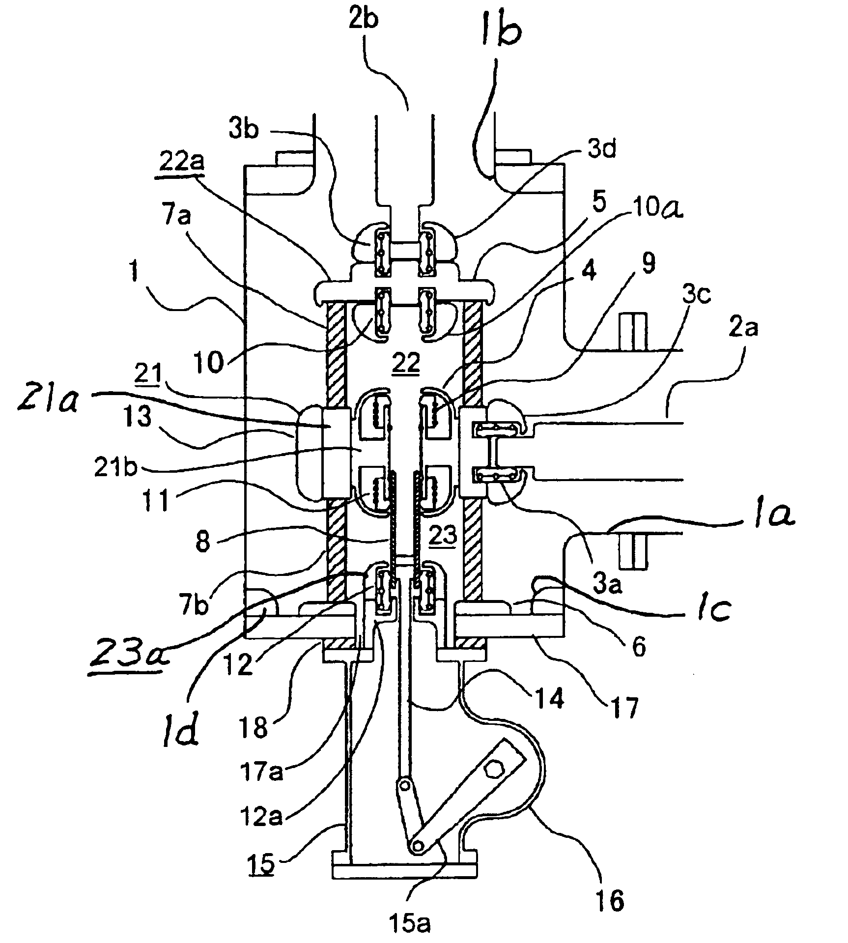
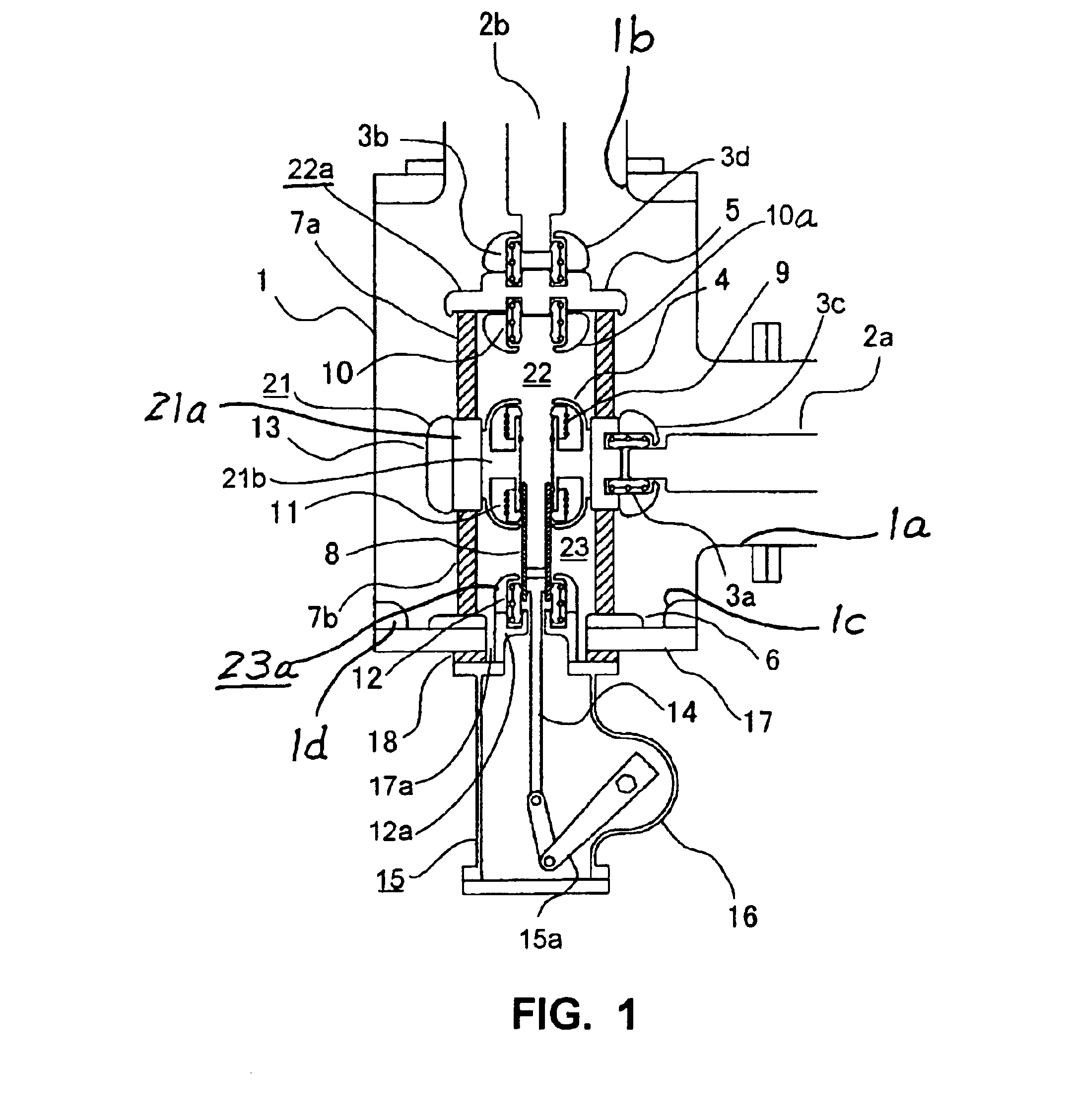
[0019]FIG. 1 shows the structures of a disconnector and a grounding switch embodying the present invention being included in a gas-insulated switchgear. The gas-insulated switchgear includes a tank 1 filled with an electrically insulating gas, a first conductor 2a and a second conductor 2b, both being disposed within the tank 1, a disconnector 22 for disconnecting the first conductor 2a from the second conductor 2b, and a grounding switch 23 for grounding the first conductor 2a when the disconnector 22 is open. The first and second conductors 2a and 2b are disposed at right angles to each other to form a branched structure in which two branches are at right angles to each other. The tank 1 is an approximately T-shaped grounding vessel combining two cylindrical parts joined at right angles to each other, and the three ends 1a, 1b and 1c of the T-shaped structure are open. The first conductor 2a is introduced into the tank 1 through the open end 1a and the second conductor 2a is intro...

embodiment 2

[0029]FIG. 4 illustrates the structure of the disconnector 22 and the grounding switch 23 in a gas-insulated switchgear shown as another embodiment of the present invention. While the gas-insulated switchgear shown as embodiment 1 in FIG. 1 has the insulation support 7b for insulation among the electrodes and the insulation adapter 18 as separate parts fastened individually to the flange 17, the gas-insulated switchfear in this embodiment has an insulation support 19 (the member equivalent to the insulation support 7b in embodiment 1) as a part formed into a single piece that passes through an opening 17a of the flange 17 and extends across the flange 17 as far as the outside of the flange 17. In the illustrated embodiment, the end of the insulation support 19 reaching to the outside of the flange 17 (the lower end in the Figure) is fastened to the outer surface of the flange 17 and sealed airtight, and the operating mechanism 15 is mounted on this end of the flange 17. The gas-insu...

embodiment 3

[0030]FIG. 5 illustrates the structure of the disconnector 22 and the grounding switch 23 in a gas-insulated switchgear shown as still another embodiment of the present invention. The gas-insulated switchgear in this embodiment is provided with an electrode 24 that has a single contact (contact 20) in the middle section of the shield 4, different from the gas-insulated switchgear shown as embodiment 1 in FIG. 1 that is provided with the electrode 21 that has two contacts 9 and 11. The movable contact 8 is therefore in contact with the contact 20 in any position in its movement back and forth to cause or break a bridge over a gap between fixed contacts, and the contact 20 of the electrode 24 serves as contact commonly for the disconnector 22 and the grounding switch 23. The gas-insulated switchgear of FIG. 5 embodies a structure attaining a further reduction in the number of parts while retaining the advantages of the switchgears shown as embodiments 1 and Embodiment 4

[0031]FIG. 6 il...


PUM


Abstract

A gas-insulated switchgear includes a tank filled with an electrically insulating gas, first and second conductors disposed within the tank, a disconnector for disconnecting the first conductor and the second conductor from each other, and a grounding switch for grounding the first conductor when the disconnector is in an open position. The disconnector includes a first and second fixed electrode disposed on the first and second conductors, respectively, a bridging movable electrode that is always maintained in contact with the first electrode and that is slidably movable for contacting with and separating from the second fixed electrode to connect and disconnect the first and second fixed electrodes, and an operating mechanism for opening and closing operation of the movable electrode. The grounding switch includes the bridging movable electrode which is in contact with the first contact, and a third fixed grounding electrode disposed to the tank capable of contacting with the movable electrode when the movable electrode is separated from the second electrode. The operating mechanism is provided with an electrically insulating operating rod extending through the first fixed electrode in the direction of movement of the movable electrode.

Description

BACKGROUND OF THE INVENTION[0001]This invention relates to a gas-insulated switchgear, in particular to a gas-insulated switchgear including a disconnecting switch and a grounding switch.[0002]FIGS. 7 and 8 are schematic sectional views showing the internal structure of a gas-insulated switchgear 100 of the conventional type that is structurally almost same as the one including a disconnecting switch that is bent at a right angle in the middle as shown in FIG. 1 of Japanese Patent Laid-Open Hei 3-5014 and is equipped with a grounding switch as shown in FIG. 3 of Japanese Published Unexamined Patent Application Sho 60-5711.[0003]The gas-insulated switchgear shown in FIGS. 7 and 8 includes a tank 101 filled with an electrically insulating gas, a first and second conductors 102 and 103 disposed within the tank 101 and disposed at right angles to each other, a disconnecting switch or a disconnector 104 for disconnecting the conductor 102 from the conductor 103 and a grounding switch 105...

Claims


Application Information

Patent Timeline
Patent Type & Authority Patents(United States)
IPC IPC(8): H01H31/00H01H31/32H02B13/02H02B13/075
CPCH01H31/003H01H31/32
Inventor OTSUKA, TAKUYASADAKUNI, HITOSHI
Owner MITSUBISHI ELECTRIC CORP
Why Eureka
Try Eureka