Removable door check device

a door check and retraction technology, applied in the field of door check devices, can solve the problems of permanent additional moving parts, and achieve the effect of low cost and effectiv

Inactive Publication Date: 2005-09-27
EDSCHA NORTH AMERICA
View PDF14 Cites 19 Cited by
  • Summary
  • Abstract
  • Description
  • Claims
  • Application Information

AI Technical Summary

Benefits of technology

[0007]An object of the present invention is to provide a low cost and effective removable door check device that does not require contact with a hinge pin or hinge axis. An alternate or additional object of the invention is to provide a door check device that can function with hinges having standard

Problems solved by technology

A disadvantage of the this device is that it is only useable on hinges having split pins, and wherein at least one of the split pins is accessib

Method used


Image

  • Removable door check device
  • Removable door check device
  • Removable door check device

Examples


first embodiment

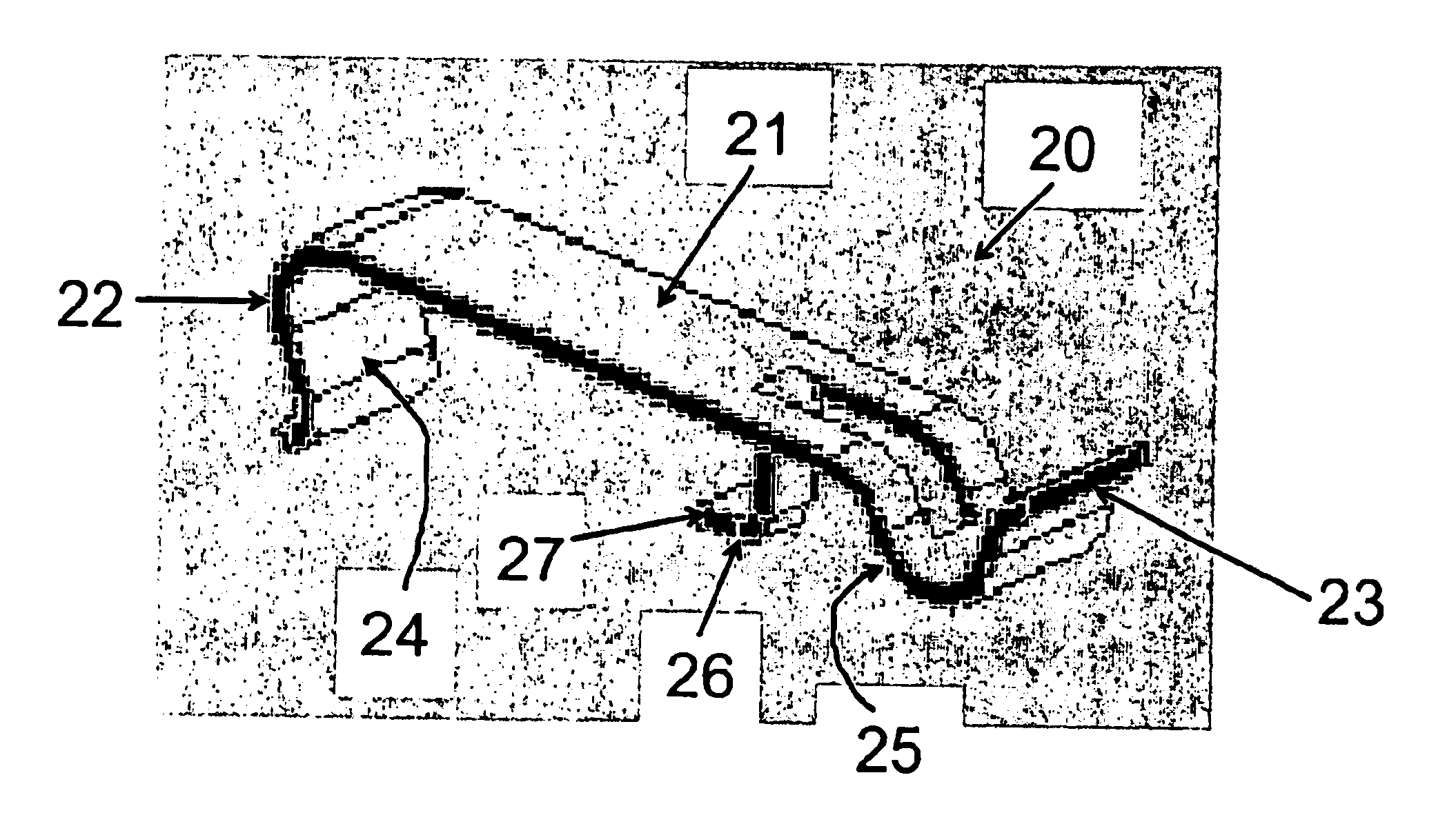
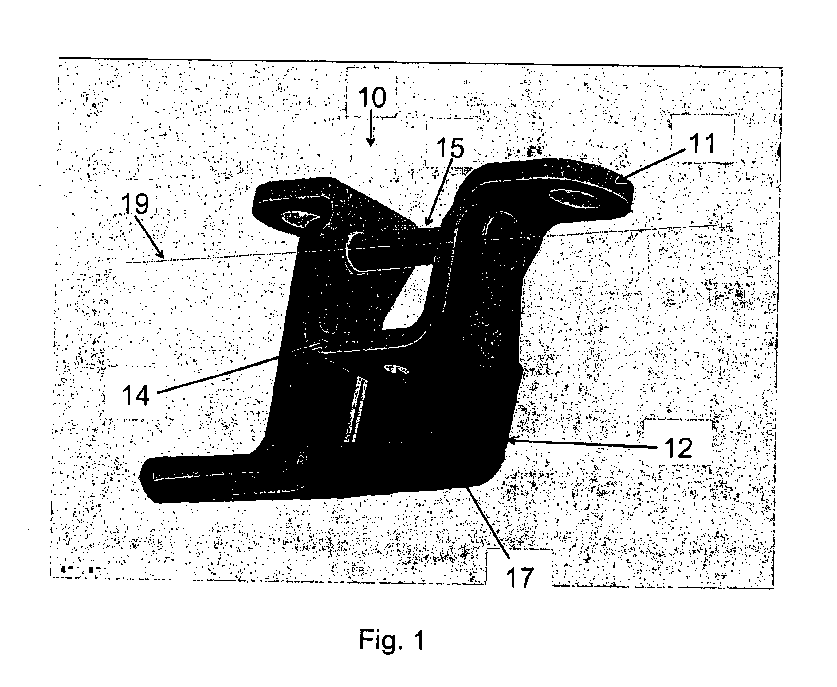
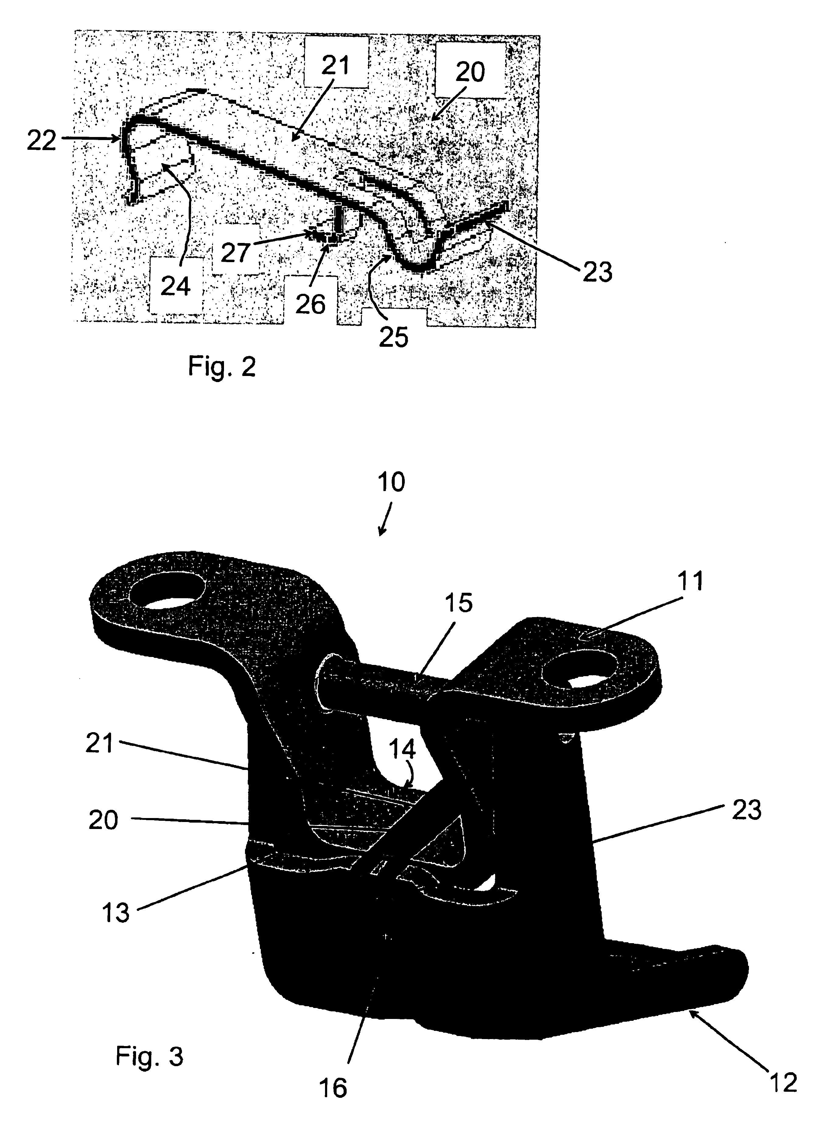
[0027]a removable door check device 20 according to the present invention is shown in FIGS. 2 and 3. Removable door check device 20 includes body 21. At one end of body 21 first contact element 22 extends downward and includes first contacting surface 24, which is configured to engage rear edge 14 of first hinge part 11 (shown in FIGS. 1 and 3). Clip element 26 extends downward from an intermediate portion of body 21 and is configured to engage front edge 13 of first hinge part 11 (shown in FIG. 3). Bent end 27 extends around a downward side of hinge part 21 in order to hold door check device 20 firmly to hinge part 11. Second contact element 23 extends from an opposite end of body 21 as first contact element 22. Second contact element 23 extends downward from body 21 and is bent again upward and includes contact surface 25 configured to engage front edge 16 of second hinge part 12.

[0028]Removable door check device 20 is preferably integrally formed of a single piece of a flexible m...

fourth embodiment

[0039]FIG. 8 shows a removable door check device 50, to be used together with a door hinge similar to door hinge 200 shown in a closed position in FIG. 7. Door check device 50 includes first element 52 extending downward from body 51 in the form of a cylindrical pin, which is configured to engage hole 18 in first hinge part 11 of hinge 200. Like door check device 30 shown in FIGS. 4 and 5, door check device 50 is preferably integrally formed of a single piece of material, such as being molded from a resilient thermoplastic material. Cylindrical pin 52 includes an outer flange 61 which is configured to engage a distal end of hole 18, and thereby to keep door check device 50 firmly attached to first hinge part 11 of hinge 200. First contacting surface 54, which includes a portion of the outer surface of pin 52 between flange 61 and body 51, engages an inner surface of hole 18 of first hinge part 11. End 61 of pin 52 has a smaller diameter than flange 61 (and than hole 18) and is cone ...


PUM


Abstract

A removable door check device for use for use with a door hinge for holding a vehicle door in an opened position. The removable door check device includes a body, a first contact element extending from the body and having a first contacting surface, and a second contact element extending from the body and having a second contacting surface facing the first contacting surface. The first and second contacting surfaces are moveable with respect to each other to permit release of the door check device. In addition, a door hinge includes a first hinge part, a second hinge part pivotally connected to the first hinge part, and a removable door check device. The removable door check device includes a first contact element having a first contacting surface configured to engage the first hinge part and a second contact element having a second contacting surface facing the first contacting surface and configured to engage the second hinge part when the door hinge is in the opened position.

Description

BACKGROUND OF THE INVENTION[0001]The present invention relates generally to a door check device, and more particularly to a removable door check device for use with a door hinge for holding a vehicle door in an opened position. The present invention also relates to a door hinge including a removable door check device.[0002]During the manufacture of vehicles, the vehicle body and doors are typically painted together in a single process step after the doors have been mounted to the vehicle. It may be desirable to keep the vehicle doors held in an opened position temporarily so that the certain painting operations can be performed.[0003]U.S. Pat. No. 6,334,236 describes a vehicle door prop clip for a vehicle hinge having split hinge pins. The prop clip is mounted onto the vehicle hinge by placing a sleeve member of the prop clip over one of the hinge pins in the split-pin hinge. The prop clip includes two lobes which compress as one hinge part is pivoted with respect to the other hinge...

Claims


Application Information

Patent Timeline
IPC IPC(8): E05D11/00E05D11/10E05D5/06E05D5/00E05D7/10B60J5/04E05C17/22
CPCE05D11/1057E05D11/1085E05D5/062E05D11/00Y10T16/615E05Y2800/692E05Y2900/531Y10S16/17Y10T16/61E05Y2201/218
Inventor SPALDING, CRAIGO'BRIEN, AARONMILAM, MARC
Owner EDSCHA NORTH AMERICA
Why Eureka
Try Eureka