Window covering with improved anchor for operating cord

Active Publication Date: 2005-09-27
HUNTER DOUGLAS INC
View PDF20 Cites 30 Cited by
  • Summary
  • Abstract
  • Description
  • Claims
  • Application Information

AI Technical Summary

Benefits of technology

[0010]The anchor is designed such that the cord can be wrapped around one or more of the ribs in the elongated body and selectively moved along its length relative to the elongated body in a simplified manner. Each rib has edges of different configurations with some edges being designed to grip the cord and other edges being contoured to allow easy slippage of the cord relative to the rib. The varying configurations of the edges of the ribs allow the cord to be moved and selectively anchored at any desired location along the length of the cord in a simple manner and once the cord has been desirably positioned relative to the elongated body, the cap is inserted into the open end of the elongated body to pinch and otherwise trap a free end of the cord that is adjacent to the elongated body.

Problems solved by technology

As will be appreciated, however, it is difficult to tie a knot at a precise location along the length of a cord or the like and, accordingly, it is difficult to obtain precisely the same effective length in each operative element.
Such systems are more effective than simply knotting the operative elements, but as will be appreciated, it is difficult to hold the operative element at a precise location along its length relative to the pocket when inserting the ferrule into the pocket and accordingly, this system has also proven to be less than fully satisfactory.

Method used


Image

  • Window covering with improved anchor for operating cord
  • Window covering with improved anchor for operating cord
  • Window covering with improved anchor for operating cord

Examples


Embodiment Construction

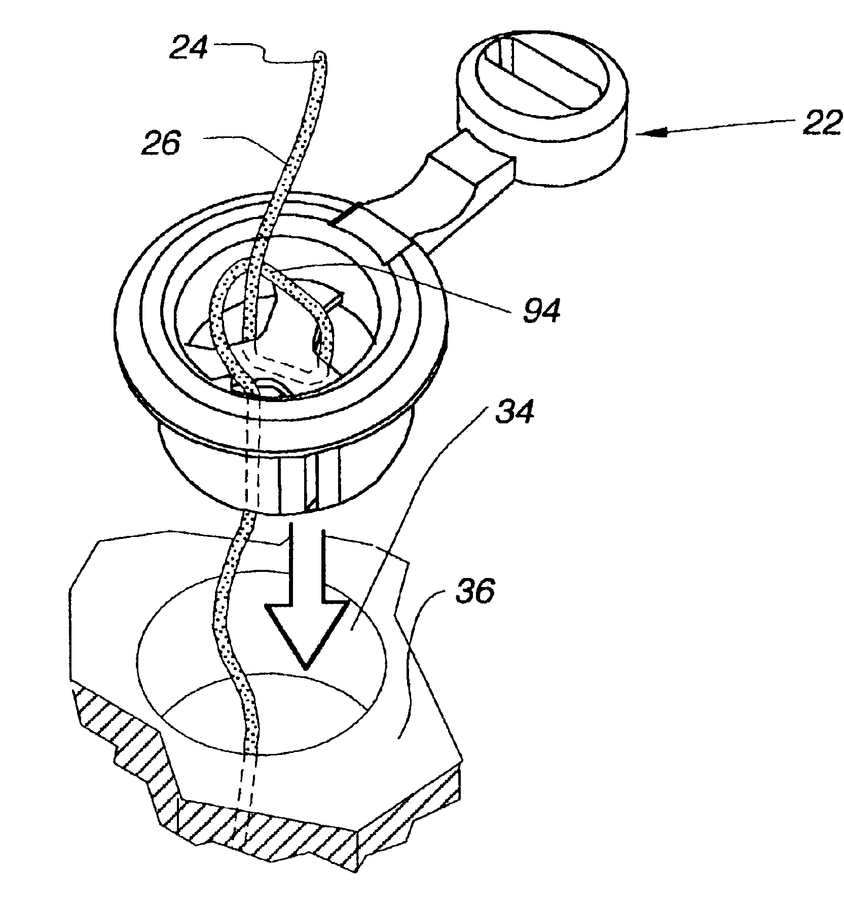
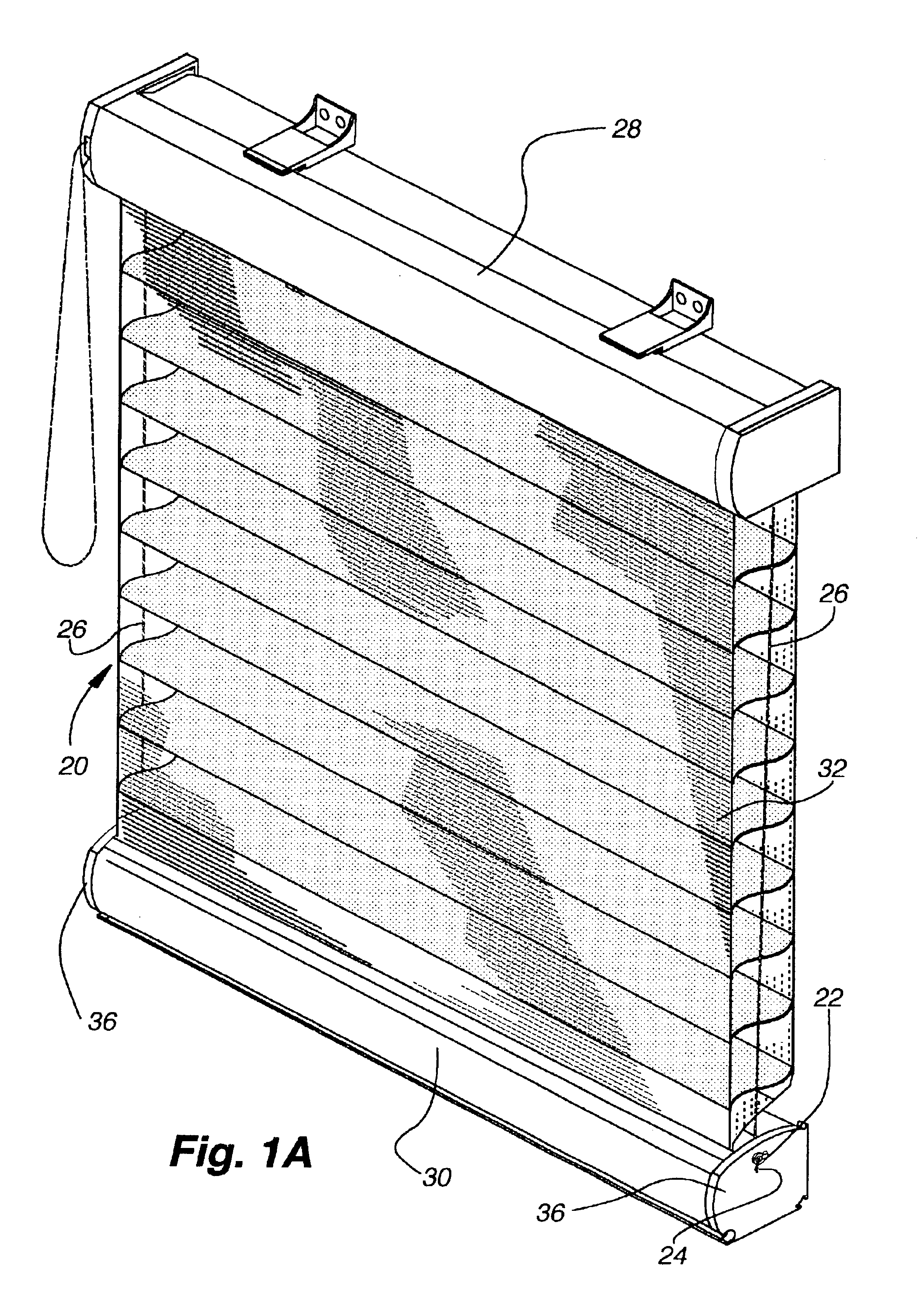
[0031]With reference first to FIG. 1A, a covering 20 for an architectural opening (not shown) is illustrated that encompasses the anchor 22 of the present invention for securing a free end 24 of an operative element to an operative component of the covering. The covering can be seen to include a head rail 28, a bottom rail 30, and a blind material 32 extending therebetween. The blind material could be any material commonly found in coverings for architectural openings such as sheets of fabric, cellular material, Venetian blind slats, or the like. As in most retractable coverings for architectural openings, the covering further includes operative elements 26 in the form of elongated cords, ribbons, tapes or the like that are used for many purposes, but in the illustrated embodiment, as a lift cord that extends from the headrail to the bottom rail with the lower free end 24 of the lift cord being secured to the bottom rail with the anchor of the present invention. While the lift cord ...


PUM


Abstract

A covering for an architectural opening includes a head rail, a bottom rail, and a blind material extending therebetween in addition to an operating element or lift cord extending from the head rail to the bottom rail and an improved anchoring system for securing the lower free end of the lift cord to the bottom rail. The anchor includes a body adapted to be inserted into an opening in the bottom rail with the body having radiating ribs at one end defining passages therebetween such that the lift cord can be selectively wrapped around the ribs in a predetermined manner to secure the lift cord to the anchor at a predetermined location along the length of the lift cord. A cap is provided on the anchor for further securing the cord to the body by pinching the cord between the cap and an internal surface of the body.

Description

CROSS REFERENCE TO RELATED APPLICATIONS[0001]This application claims the benefit of U.S. provisional application No. 60 / 390,020, filed Jun. 17, 2002, and is hereby incorporated by referenced as if fully disclosed herein.BACKGROUND OF THE INVENTION[0002]1. Field of the Invention[0003]The present invention relates generally to coverings for architectural openings and more particularly to an anchor for securing one end of an operating cord for the covering in a bottom rail or other component of the covering.[0004]2. Description of the Relevant Art[0005]Retractable coverings for architectural openings such as windows, doors, archways, or the like, typically include a head rail, a bottom rail, and a blind material extending between the head rail and bottom rail. The blind material can be many different materials such as sheets of fabric, horizontal slats as found in Venetian blinds, cellular shade material or the like. The covering further typically includes at least one operating elemen...

Claims


Application Information

Patent Timeline
IPC IPC(8): A47H3/00A47H3/02
CPCA47H3/02Y10T24/39Y10T16/665Y10T16/68
Inventor GAUDYN, ERWINWISECUP, STEPHEN T.AKINS, TERRY L.
Owner HUNTER DOUGLAS INC
Why Eureka
Try Eureka