Palletless loading structure for storage system

a storage system and pallet technology, applied in the field of palletless loading structure for storage systems, can solve the problems of complex loading configuration, affecting the efficiency of loading and unloading, etc., and achieve the effect of quick and precise storage of a wide range of goods, easy and safe storage, and simple and safe storag

Inactive Publication Date: 2005-09-27
LEE WAN YOUNG
View PDF12 Cites 54 Cited by
  • Summary
  • Abstract
  • Description
  • Claims
  • Application Information

AI Technical Summary

Benefits of technology

[0035]Accordingly, when a transporting fork is advanced into or retreated out of a storage fork, the present invention enables any one of fork bars to be lifted up to at least minimum allowance gap relative to the other. It is possible for good W to be quickly and safely taken into or taken out of a storage space without causing any interference between the fork and its relative fork bar and also excludes the use of a separate pallet.
[0036]Also, the fork bars are mounted to the upper surface of the support beam to be not separated from the storage fork and form a single row of fork bars. It is possible to easily, simply and safely store a variety of goods on the storage fork independent of its size, even if the sizes of the goods do not exceed a predetermined size of each storage space of the racks. Therefore, the palletless loading structure accomplishes the quick and precise loading or unloading of goods into or from storage spaces of racks, thereby enhancing its operational reliability, achieving the effective management and structural stability of the storage system.

Problems solved by technology

However, the conventional storage system needs a plurality of support pallets and at least one traction unit, separately, for the storage and shipment, so its loading configuration becomes complex.
Further, a gross load imposed on the racks R as well as on the traction unit T during carrying goods W along with the support pallet is increased by a weight of a plurality of support pallets or one pallet and has to be reflected into the total configuration design of the storage system or the traction unit T. In case of the traction unit T, the support pallet has a bad effect on a power and time used up in carrying goods W.
For it, the conventional storage system has a disadvantage in that it takes much time in putting goods into or taking goods out of the storage spaces of the loading stages following by the separate dealing of the support pallet.
However, the vertical storage apparatus free of a pallet has a problem in that the moving distance of the elevation fork 2 is relatively longer, because the elevation fork 2 passes through or cross the storage fork 1, vertically, during a loading or unloading operation.
It takes a relative longer time for the storage and shipment of goods W, so that the vertical storage apparatus fails to reduce the time consumption during a loading or unloading operation.
However, the loading structure is designed such that the lift fork 7 passes through the support bars 6 from above its upper portion to below its lower portion thereby to return to its original position, so it has a limitation to the time reduction in taking in or out of goods W due to a relatively longer traveling distance.
It has a limitation to a size of goods W that can be stored in the storage system.

Method used


Image

  • Palletless loading structure for storage system
  • Palletless loading structure for storage system
  • Palletless loading structure for storage system

Examples


first embodiment

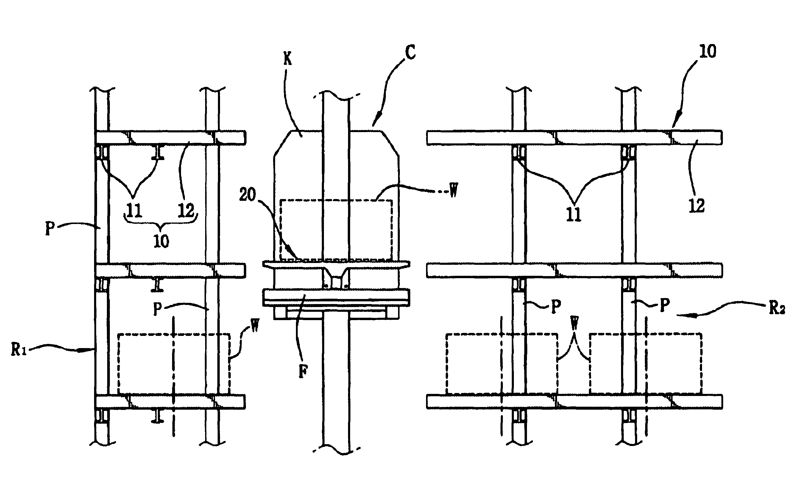
[0050]FIGS. 5, 6 and 7A to 7D show a palletless loading structure for a storage system and its operation according to the present invention. As shown in the drawings, the palletless loading structure comprises a plurality of storage forks 10 fixedly provided in storage spaces of racks R to support firm goods W having a nearly flat bottom side thereon and a transporting for 20 for being laterally approached to or withdrawn from a storage fork 10 by means of a transporting unit operable in multi-axial directions in order to load goods W onto or unload goods W from the storage fork 10.

[0051]For ease of description, a beam which connects posts P to each another widthwise in racks R in the drawings will be referred to as a horizontal beam B, and a beam which connects posts P to each another lengthwise in racks R in the drawings will be referred to as a connecting beam.

[0052]The storage fork 10 comprises a first support beam 11 and a plurality of storage fork bars 12 mounted on the upper ...

second embodiment

[0077]FIGS. 8 and 9A to 9D show a palletless loading structure for a storage system according to the present invention.

[0078]According to the second embodiment, the palletless loading structure is constructed contrary to those of a transporting fork bar of a transporting fork and a storage fork bar of a storage fork according to the primary embodiment. That is, a height “a” of a storage fork bar 32 is set to be less than a height “b” of a transporting fork bar 42 by at least operational allowance gap “g1” or “g2”. In addition, a lower projecting tap 33 having a predetermined height “s2” is projected from the lower surface of each storage fork bar 32, the lower surface of which is mounted to a support beam 31.

[0079]The height “s2” of the lower projecting tap is determined to be larger than a sum of the upper and lower operational allowance gaps “g1” and “g2” which permits the transporting fork 40 to smoothly load goods W onto or unload them from the storage fork 30, that is, s2>g1+g2...

third embodiment

[0083]FIGS. 10 and 11A to 11D show a palletless loading structure for a storage system according to the present invention.

[0084]The palletless loading structure for the storage system is constructed according to a combination of the principles of the two embodiments. That is, a height “a” of a storage fork bar 52 of each storage fork 50 and a height “b” of a transporting fork bar 62 of a transporting fork 60 are set to be equal to each other, and lower projecting taps 53 and 63 having predetermined heights “s1” and “s2” are respectively provided on the lower surfaces of each of storage fork bars 53 and the transporting fork bars 62. The storage fork bars 52 of each storage fork 50 are mounted to a support beam 51 at the lower surfaces of the lower projecting taps 53, and the transporting fork bars 62 are mounted to a support beam 61 at the lower surfaces of the lower projecting taps 63.

[0085]The heights “s1” and “s2” of two types of lower projecting taps 63 and 53 are respectively d...


PUM


Abstract

The invention provides a palletless loading structure for a storage system which comprises a plurality of storage forks including a first support beam and a plurality of storage fork bars mounted in regular interval to cross the first support beam at a right angle; a stacker crane and a including a plurality of transporting fork bars horizontally arranged in a regular interval to be alternatively positioned between the storage fork bars and a third support beam supporting the lower middle portion of the transporting fork bar, wherein any one height of the storage fork bar transporting fork bar is set to be relatively higher than the other one, and the fork bar of a relatively lower height includes a projecting tap mounted on the lower portion thereof, the projecting tap being mounted on the supporting beam.

Description

BACKGROUND OF THE INVENTION[0001]1. Field of the Invention[0002]The present invention relates, in general, to a storage system such as automatic warehouses designed to take a great quantity of goods or many vehicles into or take them out of storage spaces on storage forks of racks in order to allow users to effectively store and manage goods or vehicles and, more particularly, to a palletless loading structure for a storage system for quickly and safely taking goods into and / or taking them out of a storage space on storage forks free of additional support pallets.[0003]2. Description of the Prior Art[0004]As well known to those skilled in the art, storage systems are a facility designed to store goods or other materials in a limited storage place and manage the stored goods or materials, effectively, which has been widely used as part of a large-scale material flow system or a warehouse in other industrial work places.[0005]As shown in FIG. 1, a conventional storage system comprises...

Claims


Application Information

Patent Timeline
Patent Type & Authority Patents(United States)
IPC IPC(8): B65G1/04E04H6/18B65G1/10B65G1/14
CPCB65G1/0407E04H6/186B65G1/10
Inventor LEE, WAN YOUNG
Owner LEE WAN YOUNG
Why Eureka
Try Eureka