Electrical card connector

a technology of electrical connectors and connectors, applied in the direction of coupling devices, coupling parts engagement/disengagement, coupling device connections, etc., can solve the problems of sliding b>31/b> not being stably engaged with the insulating housing b>1, and electrical cards not being reliably connected electrically to the electrical card connectors. achieve the effect of reliable configuration

Inactive Publication Date: 2005-09-27
JESS-LINK PRODUCTS
View PDF3 Cites 12 Cited by
  • Summary
  • Abstract
  • Description
  • Claims
  • Application Information

AI Technical Summary

Benefits of technology

[0014]An objective of the present invention is to provide an electrical card connector, which limits the upward displacement of the guid

Problems solved by technology

However, due to the configuration of the conventional electrical card connector, the slider 31 is likely to shake vertically while sliding along the slide groove 34, the

Method used


Image

  • Electrical card connector
  • Electrical card connector
  • Electrical card connector

Examples


Embodiment Construction

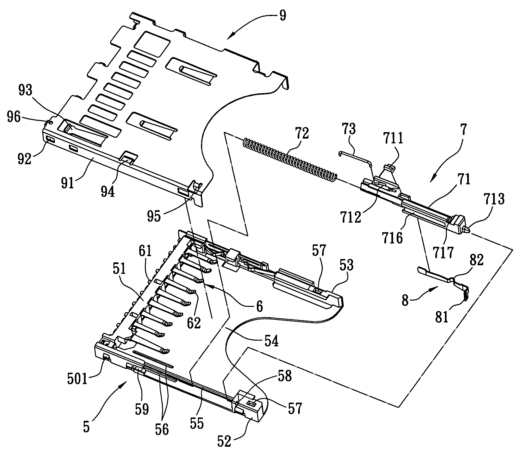
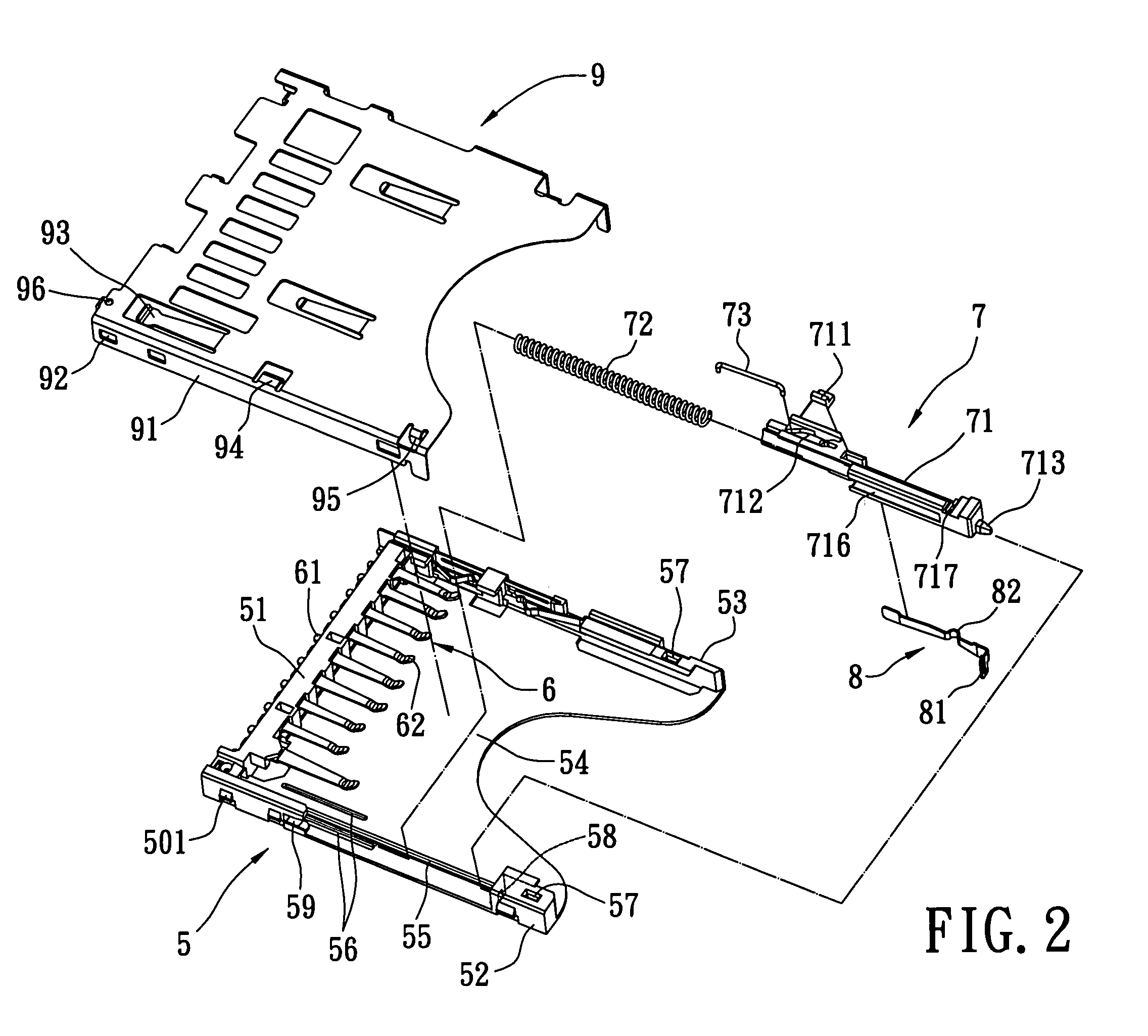
[0029]Referring to FIGS. 2–4, an electrical card connector used for receiving or ejecting an electrical card in accordance with the present invention is shown. The electrical card connector comprises an insulating housing 5, a plurality of conductive terminals, an ejector 7, a spring switch 8, and a shielding member 9. The insulating housing 5 is made of a plastic material, which includes a base portion 51, a first side arm 52 and a second side arm 53 extending parallel from the two ends of the base portion 51. They can also be convex. The base portion 51, the first side arm 52, and the second side arm 53 form a receiving cavity 54 therebetween for retaining electrical cards. The insulating housing 5 has a guide rib 55 adjacent to the first side arm 52, and two longitudinal slots 56 disposed at opposite sides of the guide rib 55 respectively. The guide rib 55 and the longitudinal slots 56 extend along a direction that is relative to inserting or ejecting electrical cards. The first ...


PUM


Abstract

The present invention is related to an electrical card connector, in which a shielding member introduced therein includes a latch, and an against portion using for abutting against a guide rod of an ejector and a top of a fixing end of the guide rod respectively so as to limit upward displacement of the guide rod. This configuration can prevent the guide rod from shaking vertically; thereby the guide rod is fixed in a stable manner. Moreover, a guide groove of the slide rod mates with a guide rib of the insulating housing so as to make the slider slide on the insulating housing stable. Thereby, electrical cards can be inserted or ejected stably and smoothly.

Description

BACKGROUND OF THE INVENTION[0001]1. Field of the Invention[0002]The present invention relates to an electrical card connector, and particularly to an electrical card connector mounted on a Print Circuit Board (PCB) for retaining an electrical card therein.[0003]2. Description of Related Art[0004]Recently, electrical cards have become widely used in the field of electronic appliances. As such, electrical card connectors are now adapted to connect electrical cards to appliances in which the electrical card connectors are mounted on the PCB of the appliance and retain electrical cards therein, allowing data to be transferred there between.[0005]Referring to FIG. 1, a conventional electrical card connector is shown, which includes an insulating housing 1, a plurality of conductive terminals 2, and an ejector 3. The insulating housing 1 has a base portion 11, a first side arm 12 and a second side arm 13 extending parallel from two ends of the base portion 11 respectively so as to form a ...

Claims


Application Information

Patent Timeline
IPC IPC(8): H01R13/62H01R12/16H01R13/633
CPCH01R13/6335H01R23/6873H01R12/00
Inventor CHEN, CHIU-KUEI
Owner JESS-LINK PRODUCTS
Why Eureka
Try Eureka