Monitoring device for the door and window

A monitoring device, door and window technology, applied in alarms, building locks, buildings, etc. that rely on breaking glass, can solve the problems of high cost, inability to distinguish windows or doors, and difficulty in realization, and achieve the effect of simple cost

Inactive Publication Date: 2008-03-12
WERU GMBH & CO KG
View PDF1 Cites 8 Cited by
  • Summary
  • Abstract
  • Description
  • Claims
  • Application Information

AI Technical Summary

Problems solved by technology

[0002] For the monitoring device known from DE 296 03 917 U1, the first sensor is formed by a magnet inserted into the multi-sided plug and a sealed contact switch arranged around the multi-sided plug, which brings about the disadvantage that the window cannot be Or the deflected position of the door is distinguished from the unlocked open position
Moreover, the structure is costly and difficult to implement
The second sensor is set on the handle fitting, and the cost is also very high
Through this monitoring device, the signal provided by the calculation unit is sent to the central monitoring station via the transmitter, but the central monitoring station cannot immediately deter and stop unauthorized persons

Method used


Image

  • Monitoring device for the door and window
  • Monitoring device for the door and window
  • Monitoring device for the door and window

Examples


Embodiment Construction

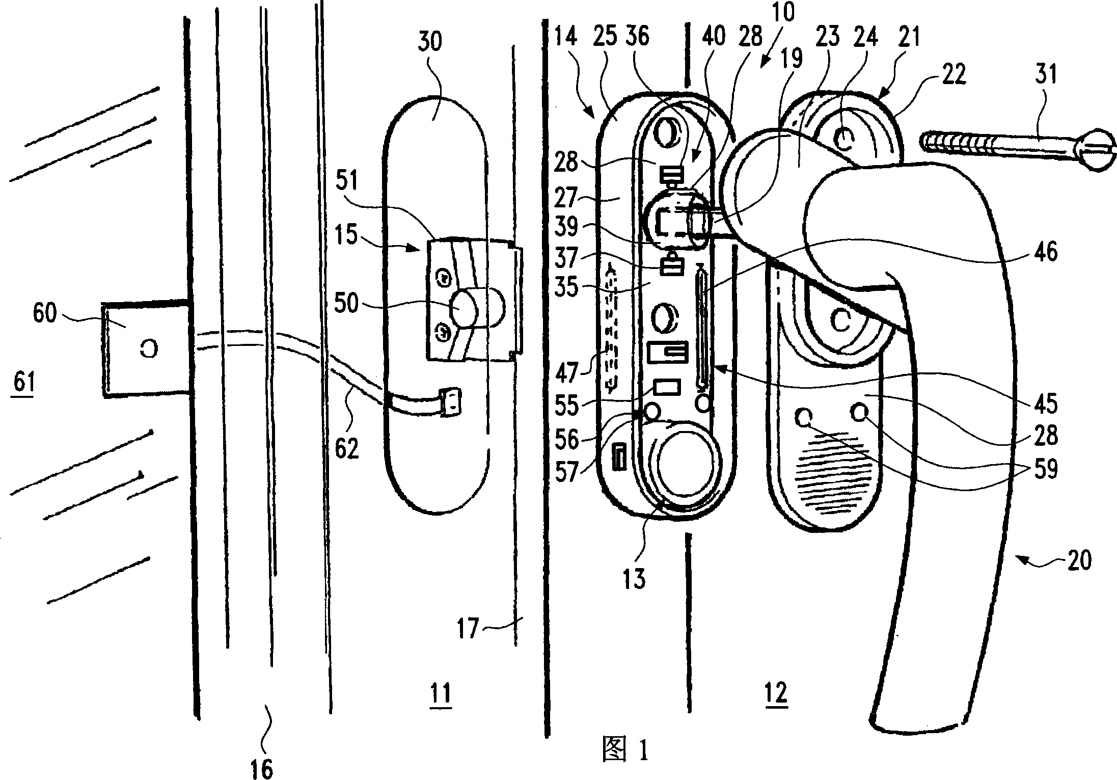
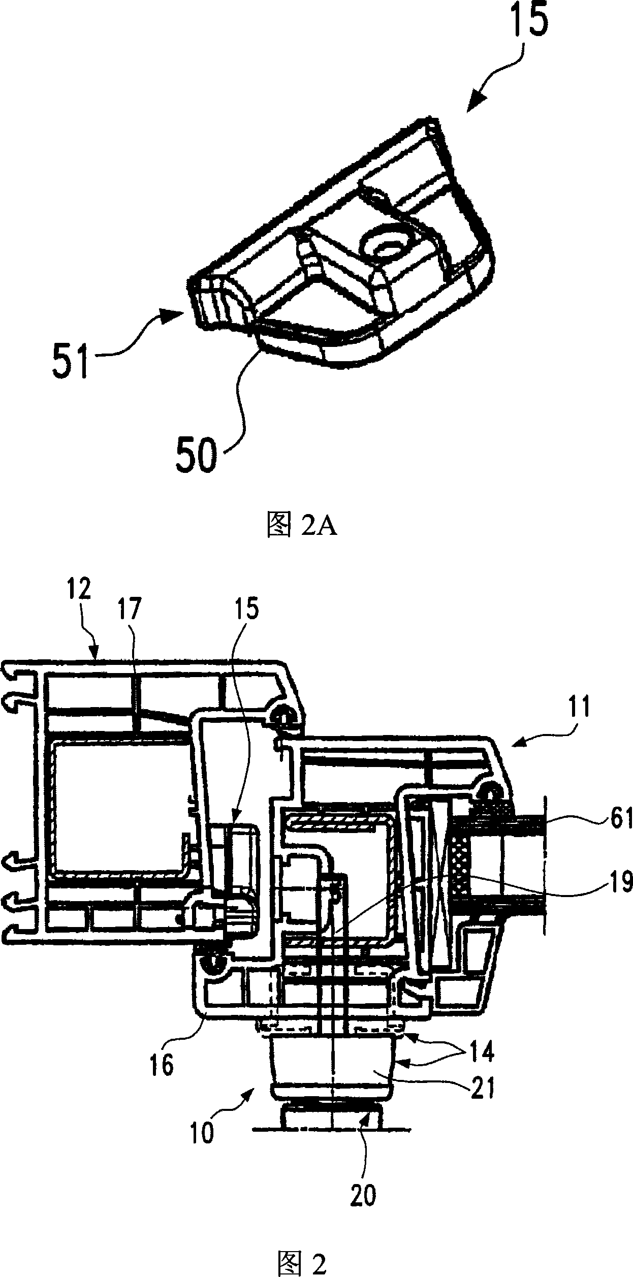
[0024] The monitoring devices 10, 110 and 210 respectively represent different embodiments or variants for recording the position of the side panel 11 of a door or window relative to the fixing frame 12 of the side panel when the side panel 11 is in the locked closed position. position, through the alarm device 13 manipulated by the monitoring devices 10, 110 and 210, an alarm is issued to unauthorized or forcible opening of the side panel 11. The monitoring devices 10 , 110 and 210 basically include a main part 14 , 114 and 214 respectively arranged and fixed in the side plate 11 , and an additional part 15 fitted and connected to the main part 14 , 114 and 214 in the fixed frame 12 . The main part 14 , 114 , 214 as well as the additional part 15 are arranged in the respective closed side frame part 16 of the side plate 11 or 17 of the fixed frame 12 . The main part 14, 114, 214 of the monitoring device 10, 110, 210 is movably connected to the handle 20, 220 of the side panel...


PUM


Abstract

The invention relates to a monitoring device (10, 110, 210) for safeguarding windows and doors whose pivotal handle (20, 220) is held on a handle fitting (21) and can be connected in a rotationally fixed manner to locking devices via a polygonal insertion pin (19), with: a housing (25, 125, 225), which at least partially houses the monitoring device (10, 110, 210) and which is passed through by the polygonal insertion pin (19); a first sensor device (40, 140) for detecting the pivotal position of the handle (20, 220); a second sensor device (45, 145) for detecting the lock position, and; an evaluating unit (55), which links and evaluates detection signals from the first and the second sensor device (40, 45; 140, 145) and optionally initiates an alarm signal. To this end, the first sensor device (40, 140) has two microswitches (36, 37; 136, 137), which are arranged at an angle to one another along the periphery of the polygonal insertion pin (19), are situated inside the housing (25, 125, 225), and which can be actuated by a switch cam (38, 138) connected to the handle (20, 220) in a rotationally fixed manner. In addition, the second sensor device (45, 145) is formed by at least one reed contact switch (46, 47), which is situated near the outer wall of the housing (25, 125, 225), and by a magnet (50), which interacts with the at least one reed contact switch (46, 47) and which is fastened to the lock-side limb (17) of the fixed frame (12) of the window or of the door.

Description

technical field [0001] The invention relates to a monitoring device for securing a door or window according to the preamble of claim 1 . Background technique [0002] For the monitoring device known from DE 296 03 917 U1, the first sensor is formed by a magnet inserted into the multi-sided plug and a sealed contact switch arranged around the multi-sided plug, which brings about the disadvantage that the window cannot be Or the deflected position of the door is distinguished from the unlocked open position. Moreover, this structure is expensive and difficult to implement. . The second sensor is provided on the handle fitting, which is also very expensive. The role of the second sensor is to determine whether the side panel of the door or window is open. With this monitoring device, the signal provided by the computing unit is sent via the transmitter to the central monitoring station, but the central monitoring station cannot immediately produce a deterrent effect on unau...

Claims


Application Information

Patent Timeline
Patent Type & Authority Applications(China)
IPC IPC(8): E05B45/06G08B13/04
CPCE05B45/06G08B13/04
Inventor T·布赫尔特
Owner WERU GMBH & CO KG
Why Eureka
Try Eureka