Sprue apparatus

a technology of sprue and sprue, which is applied in the direction of auxillary shaping apparatus, manufacturing tools, food shaping, etc., can solve the problems of waste of solidified materials, poor thermal regulation, and increase the cost of parts, and achieves reliable sealing connection, less process variation, and durable configuration

Inactive Publication Date: 2008-07-22
HUSKY INJECTION MOLDING SYST LTD
View PDF16 Cites 8 Cited by
  • Summary
  • Abstract
  • Description
  • Claims
  • Application Information

AI Technical Summary

Benefits of technology

[0017]An advantage of embodiments of the sprue apparatus of the present invention is the thermal regulation and control of a plurality of distinct thermal zones along a sprue apparatus for maintaining the molding material in the melt duct at a desired temperature and physical state to support a molding process. The plurality of thermal zones may also provide thermal regulation of spigot junctions for ensuring a reliable sealing connection between the machine nozzle and the molding apparatus.
[0018]Another advantage of embodiments of the sprue apparatus of the present invention is a durable configuration, even at the high operating temperatures required for the thixotropic molding of magnesium. In particular, vulnerable components of the sprue apparatus may be substantially isolated from applied carriage force.
[0019]Another advantage of embodiments of the sprue apparatus of the present invention is the provision of a cycling zone that controls the formation of a molding material plug used for flow control. The cycling zone is configured and controlled such that the size of the injected plug is of a consistent and minimal size and hence there is less process variation from shot to shot.

Problems solved by technology

The solidified material is wasteful and increases the cost of the part as a result of the scrap material.
There are a number of problems with known sprue apparatus that result from poor thermal regulation along the length of the sprue bushing, with only a single thermal zone dedicated to maintaining the conditions of the molding material flowing through the sprue bushing.
For example, with the single thermal control zone dedicated to the thermal regulation of molding material in support of the molding process, it is not possible to independently thermally regulate the junction between mating melt channel components; as is required with a spigot junction, to ensure a reliable seal against molding material leakage.
The leakage of molding material is of particular concern when processing light-alloys, such as magnesium in a thixomolding process, due to the possibility of rapid and uncontrolled oxidation at elevated processing temperatures.
Another problem relates to the susceptibility of known sprue apparatus to permanent deformation due to longitudinally applied carriage force, required for the purpose of maintaining a seal between the machine nozzle and the sprue apparatus, especially when the sprue apparatus is weakened at the high operating temperatures required for thixomolding magnesium.
The sprue apparatus is susceptible to permanent deformation from the compression due to its slender construction; the slender construction of the sprue apparatus provides a short heat conduction path, and therefore a fast thermal response, between heaters provided along the length of the sprue apparatus and the molding material within its melt duct.
Yet another problem relates to undesirable process fluctuations that result from the formation and ejection of sprue plugs of inconsistent length, the variations in sprue plugs may be attributed to inadequate thermal regulation and melt channel configuration.

Method used


Image

  • Sprue apparatus
  • Sprue apparatus
  • Sprue apparatus

Examples


Embodiment Construction

)

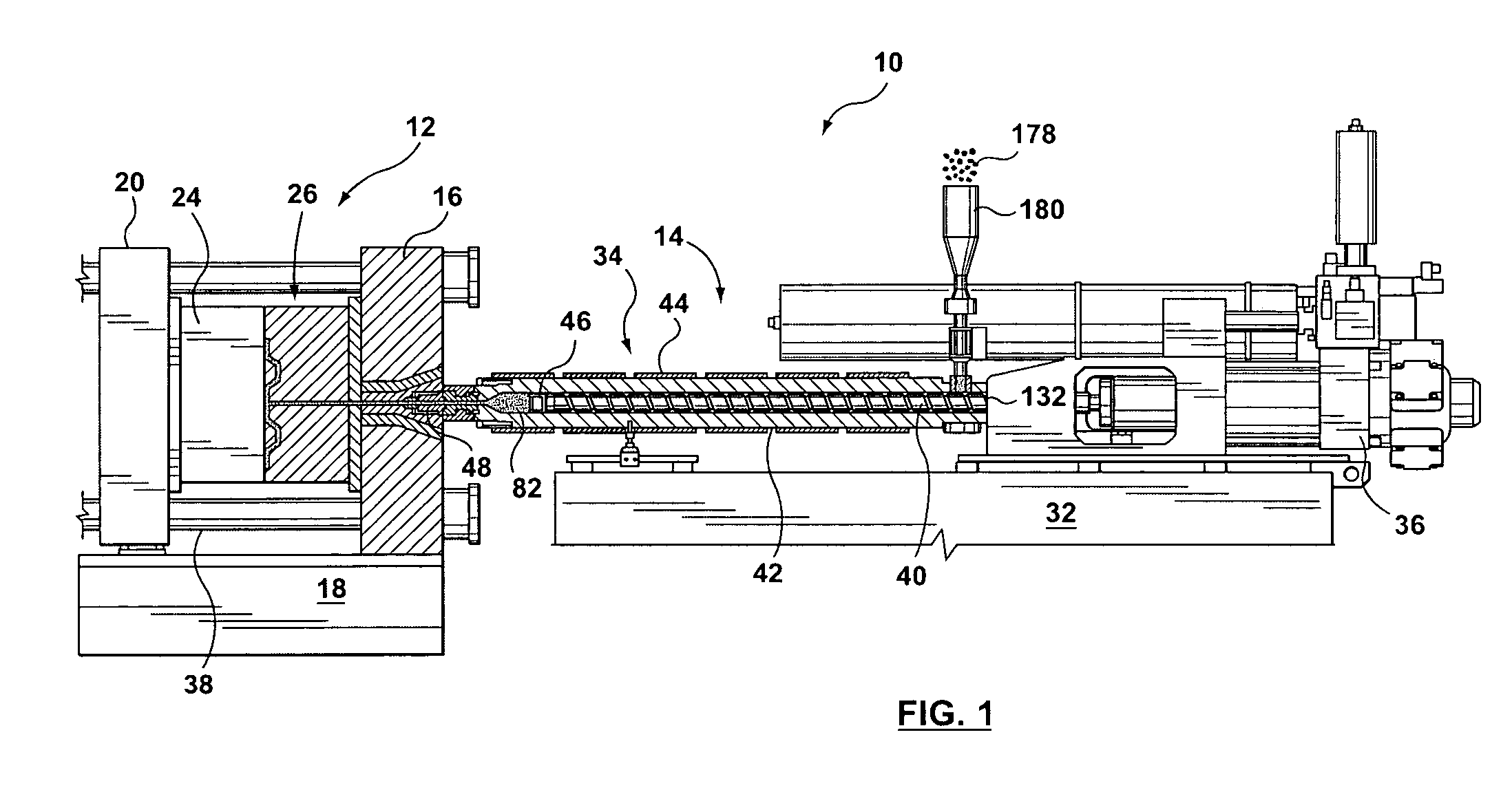
[0040]An embodiment of the invention is described in the context of (and in situ within) a typical injection molding system 10, as shown in FIG. 1.

[0041]The injection molding system 10 includes an injection unit 14 and a clamp unit 12. The injection unit 14 processes molding material for injection into a mold. The injection unit 14 includes a frame 32 that typically supports a housing for electrical components for machine, control and operation (not shown), as well as a housing for a power pack (not shown). A carriage (not shown) supports a barrel assembly 34 that includes a barrel 42. The carriage is movable relative to the frame 32 by actuation of a pair of carriage cylinders (not shown). A screw 40 is located within a bore of the barrel 42. In operation, the screw 40 is rotated and usually axially translated within the barrel 42 by a screw drive 36 in a manner that is well known in the art. The screw drive 36 may be a combination of an electric motor to rotate the screw 40, and ...


PUM

PropertyMeasurementUnit
lengthaaaaaaaaaa
carriage forceaaaaaaaaaa
temperatureaaaaaaaaaa

Abstract

A sprue apparatus for use in a molding apparatus for connecting the melt duct of a molding machine nozzle with a runner system of a molding apparatus. The sprue apparatus includes a plurality of thermal regulators that regulate a plurality of thermal zones that segment the length of the sprue apparatus for the purpose of localized temperature control in support of a molding process. The plurality of zones may be thermally regulated such as to enable a substantially leak-free junction between the machine nozzle and the molding apparatus. The sprue apparatus may include an isolating coupler that substantially isolates a heated sprue bushing from carriage force. The invention has been found particularly useful when injecting metal alloys such as magnesium based alloys when in the thixotropic state.

Description

TECHNICAL FIELD[0001]This invention broadly relates to a sprue apparatus for use in a molding apparatus. More specifically, the invention relates to a sprue apparatus for use in an injection molding or die-casting machine, and is particularly, but not exclusively, applicable to injection molding a metal material into a cavity of a mold when the material is in a thixotropic state.BACKGROUND OF THE INVENTION[0002]Sprue bushings for molding apparatus are well known in the art. For example, the book entitled “Understanding Injection Molding Technology” by Herbert Rees, copyright 1994, ISBN 1-56990-130-9, describes Hot Sprues on page 61. Essentially, sprue bushings provide a connection between the machine nozzle and the runner system of a mold for injecting at least partially molten molding material into the cavity of a mold. The at least partially molten material, sometimes called the melt, travels from the machine nozzle into a duct located within the sprue bushing and into a cavity of...

Claims


Application Information

Patent Timeline
Patent Type & Authority Patents(United States)
IPC IPC(8): B22D17/10B29C45/20B22D17/00B22D17/20B22D17/22B29C45/27
CPCB22D17/007B22D17/2015B29C45/27B29C45/2737B22D17/2272B29C2045/2754
Inventor MANDA, JAN MARIUS
Owner HUSKY INJECTION MOLDING SYST LTD
Why Eureka
Try Eureka