Linear motor with reduced cogging force

a linear motor and cogging force technology, applied in the field of linear motors, can solve the problems of large cogging force generation, increased eddy current loss, and difficulty in forming the optimum arc shape for reducing cogging force, so as to reduce cogging force and reduce variation in cogging force, the effect of not being able to reduce the cogging for

Active Publication Date: 2005-09-27
SANYO DENKI CO LTD
View PDF4 Cites 25 Cited by
  • Summary
  • Abstract
  • Description
  • Claims
  • Application Information

AI Technical Summary

Benefits of technology

[0004]An object of the present invention is therefore to provide a linear motor in which it is easy to shape the magnetic pole surfaces of the pole teeth at both ends of a pole tooth row (16) constituted by a plurality of pole teeth so as to be suitable for reducing cogging force.
[0005]Another object of the present invention is to provide a linear motor in which even if the curved magnetic pole surfaces located at both ends of a pole tooth row constituted by a plurality of pole teeth have the same width dimension, the curved magnetic pole surfaces have a magnetic resistance pattern desirable for magnetically reducing the cogging force.
[0006]Still another object of the present invention is to provide a linear motor that can reduce eddy current loss.

Problems solved by technology

In the linear motor of this type, however, large cogging force is generated.
Thus, it was difficult to form the optimum arc shape for reducing the cogging force.
Further, since the processed metal plate is employed, eddy current loss increases.

Method used


Image

  • Linear motor with reduced cogging force
  • Linear motor with reduced cogging force
  • Linear motor with reduced cogging force

Examples


Embodiment Construction

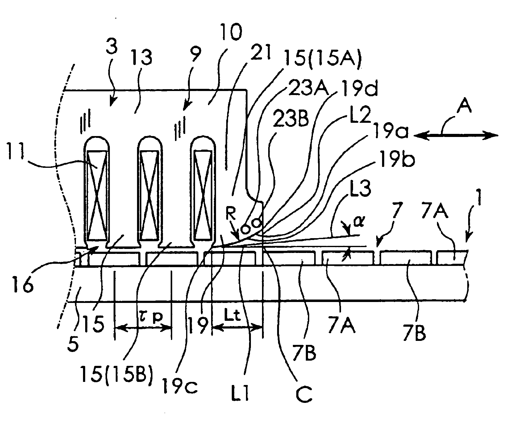
[0021]The best mode for carrying out the present invention will be described with reference to the appended drawings. FIG. 1 is a schematic diagram used to explain the construction of a linear motor according to a first embodiment of the present invention. FIG. 1 shows part of a stator 1 and part of a movable element 3. As shown in FIG. 1, the linear motor according to this embodiment includes the stator 1 and the movable element 3. The stator 1 has a structure provided with a magnetic pole row 7 on a base 5. The magnetic pole row 7 is constituted by alternately arranging a plurality of N-pole permanent magnets 7A and a plurality of S-pole permanent magnets 7B.

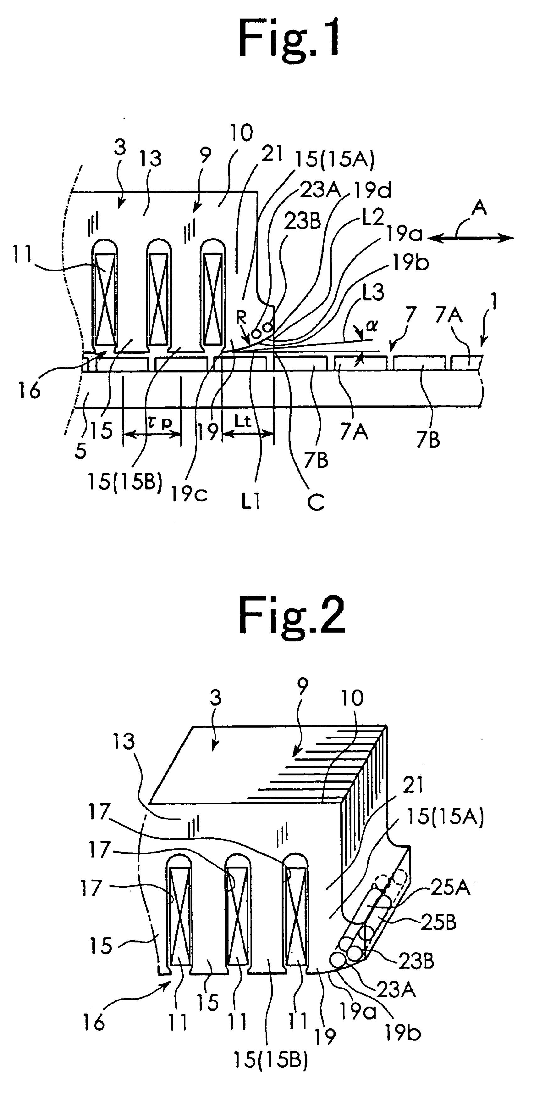
[0022]The movable element 3 is movably supported by supporting means not shown, relative to the stator 1. The movable element 3 includes an armature constituted by a core 9 and multi-phase exciting windings 11 as shown in a perspective view of FIG. 2. The core 9 is constituted by laminating a plurality of electromagnetic steel...


PUM


Abstract

A linear motor in which the shape of magnetic pole surfaces of pole teeth located at both ends of a plurality of pole teeth can be easily formed to be suitable for reducing cogging force. Each of magnetic pole surfaces 19a of pole teeth 15A located at both ends of a plurality of pole teeth 15 is constituted by an arc-shaped curved surface that is curved so that a gap from a stator 1 increases with increasing distance from other adjacent pole tooth 15B. Through holes 23A and 23B that extend in the laminating direction of electromagnetic steel plates 10 are formed in the vicinity of the magnetic pole surfaces 19a of the pole teeth 15A. Inside the through holes 23A and 23B, magnetic pieces, which are shorter than the thickness of the electromagnetic steel plates in their laminating direction, are arranged so as to leave spaces at both ends of the through holes 23A and 23B.

Description

BACKGROUND OF THE INVENTION[0001]The present invention relates to a linear motor.[0002]As an example of a linear motor in which a movable element reciprocates linearly relative to a stator, the linear motor has an armature and at least one row of magnetic poles formed by juxtaposedly arranging a plurality of permanent magnets. The armature has a core which is constituted by laminating a plurality of electromagnetic steel plates and exciting windings. The core has a yoke that extends linearly in a direction orthogonal to the direction in which the electromagnetic steel plates are laminated, and a plurality of pole teeth that protrude from the yoke toward the magnetic pole row side and have magnetic pole surfaces opposed to the row of magnetic poles or magnetic pole row at their ends. A plurality of the exciting windings excite the pole teeth. In the linear motor of this type, however, large cogging force is generated. Thus, in order to solve this problem, there has been proposed a li...

Claims


Application Information

Patent Timeline
Patent Type & Authority Patents(United States)
IPC IPC(8): H02K41/03H02K41/02
CPCH02K41/031H02K15/03H02K33/18
Inventor SUGITA, SATOSHIMISAWA, YASUSHI
Owner SANYO DENKI CO LTD
Why Eureka
Try Eureka