Image reading device and storage medium storing control procedure for image reading device

a reading device and image technology, applied in the direction of optical elements, television systems, instruments, etc., can solve the problems of difficult detection of focus position, image reading device cannot form accurate images at light-receiving surfaces, image reading device cannot output high-quality image data, etc., to achieve accurate autofocusing

Inactive Publication Date: 2005-09-27
NIKON CORP
View PDF4 Cites 39 Cited by
  • Summary
  • Abstract
  • Description
  • Claims
  • Application Information

AI Technical Summary

Benefits of technology

[0036]An object of the present invention is to provide an image reading device capable of implementing accurate autofocusing.

Problems solved by technology

Namely, due to the focal displacement occurring at the reading optical system, the image reading device cannot form an accurate image at the light-receiving surface of the image-capturing element such as a CCD line sensor which reads the original image.
As a result, the image reading device cannot output high quality image data.
First, in the image reading device in the prior art, a plurality of contrast values are obtained by changing the positional relationship between the original and the reading optical system by one step at a time. In such a case, if the plurality of contrast values thus obtained vary only to a small degree among themselves, it is difficult to detect the focused position.
Thus, it is difficult to determine the focused position.
However, the image reading device may make an erroneous decision with respect to the contrast value peak position if the contrast values vary only to a small degree as shown in FIG.
This results in a problem in that the image reading device may make an error in determining the focused position.
Secondly, in autofocusing achieved in the image reading device in the prior art, it is difficult to detect the focused position located in an area where the composition of the image on the original changes drastically.
For this reason, the correct contrast peak position cannot be detected and, instead, an erroneous contrast peak position is detected.
This leads to a problem in that the image reading device in the prior art detects an erroneous focused position.

Method used


Image

  • Image reading device and storage medium storing control procedure for image reading device
  • Image reading device and storage medium storing control procedure for image reading device
  • Image reading device and storage medium storing control procedure for image reading device

Examples


Embodiment Construction

[0088]The following is an explanation of the embodiments of the present invention, given in reference to the attached drawings.

[0089]FIGS. 1-11 illustrate an embodiment of the image reading device according to the present invention.

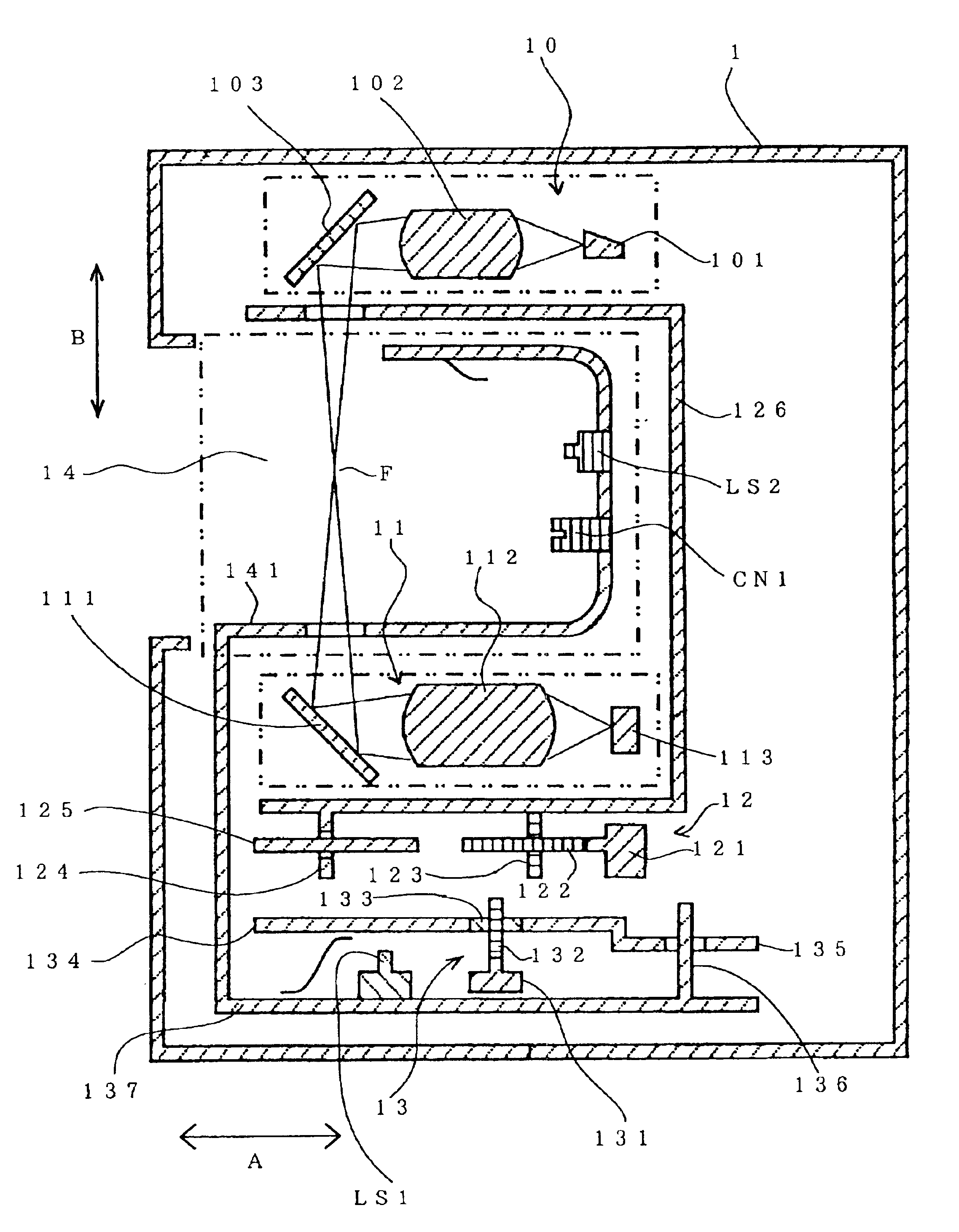
[0090]FIG. 1 illustrates the mechanical structure of a main unit 1 of the image reading device adopting the present invention. As shown in FIG. 1, the main unit 1 primarily comprises an illuminating unit 10 that radiates light on an original, a reading unit 11 that receives light irradiated by the illuminating unit 10 and outputs image data, a scanning mechanism 12 that moves the illuminating unit 10 and the reading unit 11 along the sub-scanning direction indicated by the arrow A, a focusing mechanism 13 that moves the illuminating unit 10, the reading unit 11 and the scanning mechanism 12 along the direction indicated by the arrow B and an adapter insertion unit 14.

[0091]The illuminating unit 10 is constituted of a light source 101 that is capable of em...


PUM


Abstract

In addition to an autofocusing operation performed under visible light, an autofocusing operation is also performed under infrared light. By using infrared light, changes in the contrast can be detected accurately regardless of the character of the image. As a result, the focused position can be detected with a high degree of accuracy even in a dark image or an image in which the character of the image changes drastically. In addition, by ascertaining the difference between the infrared light focused position and the visible light focused position and correcting with the infrared light focused position, a focused matched position can be detected with an even higher degree of accuracy.

Description

[0001]This application is a continuation in part of U.S. patent application Ser. No. 09 / 487,807 filed Jan. 20, 2000 now abandoned.INCORPORATION BY REFERENCE[0002]The disclosure of the following priority applications are herein incorporated by reference:[0003]Japanese Patent Application No. 11-14322, filed Jan. 22, 1999,[0004]Japanese Patent Application No. 2000-13292, filed Jan. 21, 2000BACKGROUND OF THE INVENTION[0005]1. Field of the Invention[0006]The present invention relates to an image reading device that optically reads an image on an original such as photographic film by irradiating light onto the original and a storage medium that stores a control procedure implemented on the image reading device. More specifically, the present invention relates to an image reading device provided with an autofocus mechanism that uses an infrared light to achieve an accurate read of the image on the original and a storage medium that stores a control procedure to be implemented on the image ...

Claims


Application Information

Patent Timeline
Patent Type & Authority Patents(United States)
IPC IPC(8): G02B27/02G02B7/36H04N1/03H04N1/00
CPCG02B7/36G02B27/021H04N1/00267H04N1/02409H04N1/03H04N1/00249
Inventor FUJINAWA, NOBUHIRO
Owner NIKON CORP
Why Eureka
Try Eureka