
Storage apparatus and control method therefor

a technology of storage apparatus and control method, which is applied in the direction of record information storage, liquid/fluent solid measurement, instruments, etc., can solve the problems of miniaturization and cost, and achieve the effect of reducing noise and saving power

Inactive Publication Date: 2005-09-27
HITACHI LTD
View PDF16 Cites 52 Cited by
  • Summary
  • Abstract
  • Description
  • Claims
  • Application Information

AI Technical Summary

Benefits of technology

[0008]An object of the present invention is to provide a storage apparatus and a storage apparatus control method enabling the storage apparatus to be controlled in a state desirable for power saving and noise reduction.
[0011]According to the present invention, it becomes possible to, for example, control a storage apparatus in a preferable manner for saving power and reducing noise.

Problems solved by technology

For this reason, problems in miniaturization and cost arise.

Method used


Image

  • Storage apparatus and control method therefor
  • Storage apparatus and control method therefor
  • Storage apparatus and control method therefor

Examples


Embodiment Construction

[0021]The preferred embodiments of the present invention are described in detail by referring to the accompanying diagrams below.

Outline of the Disclosure

[0022]At least the following will be apparent in accordance with the present specification and accompanying drawings.

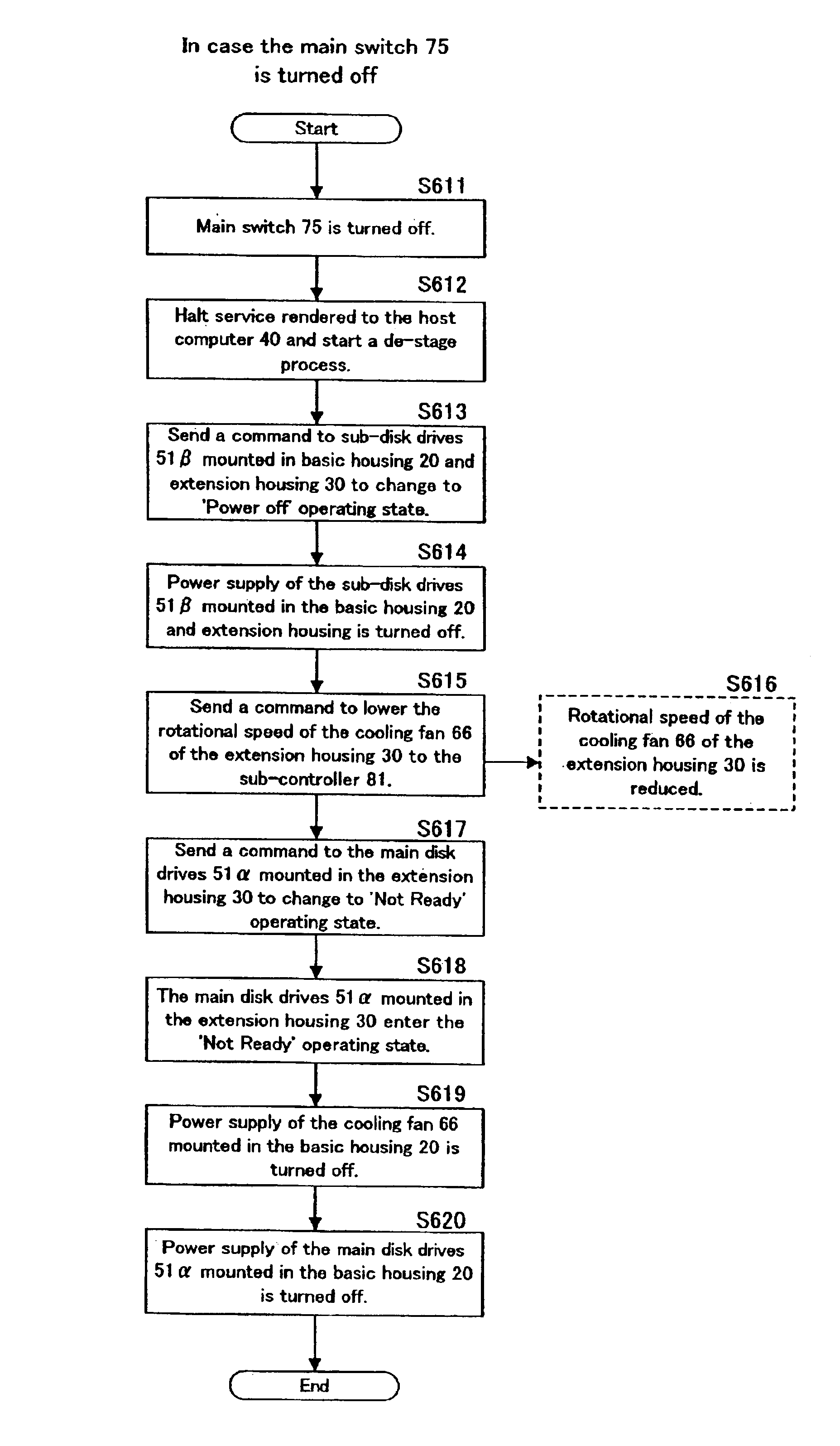
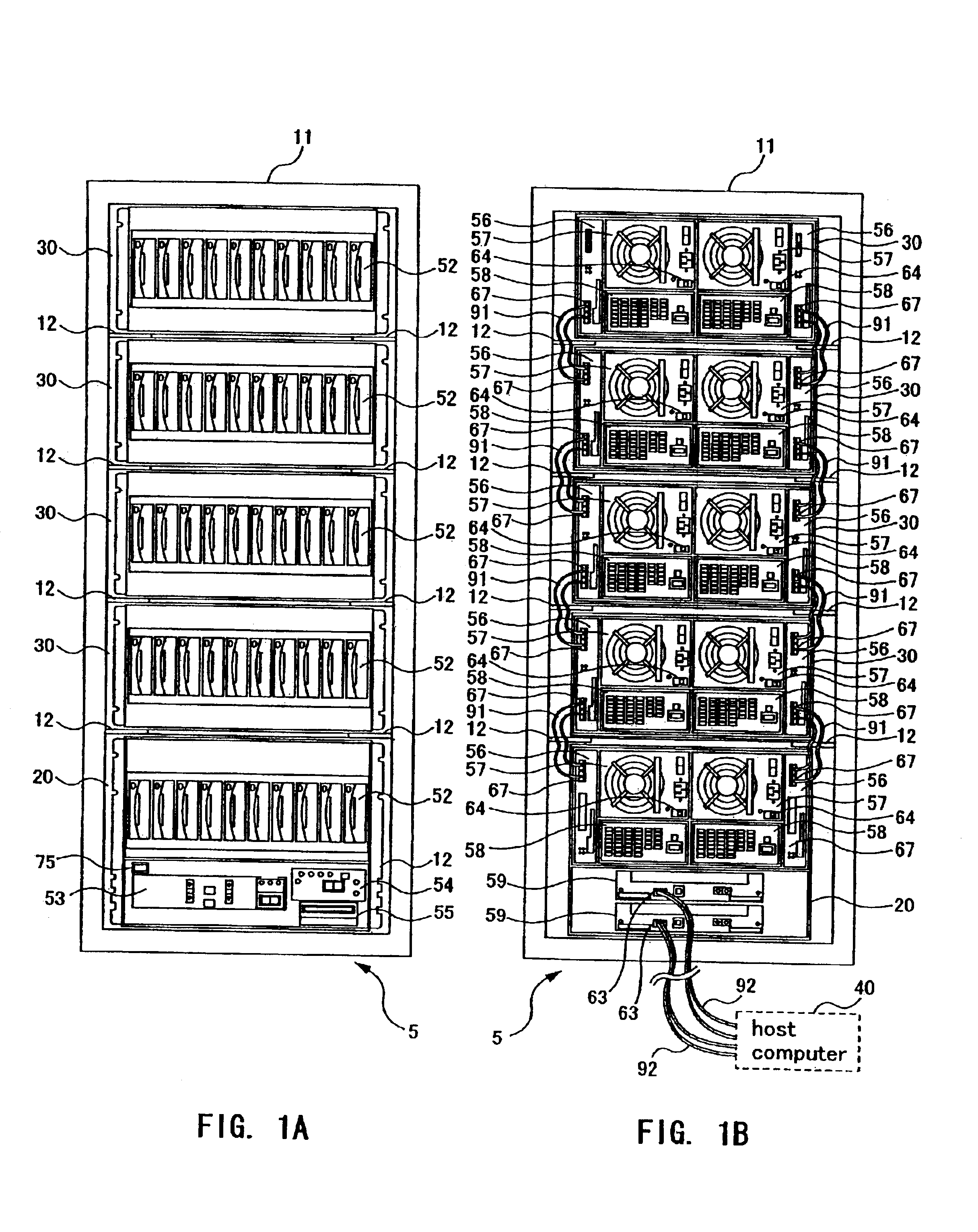
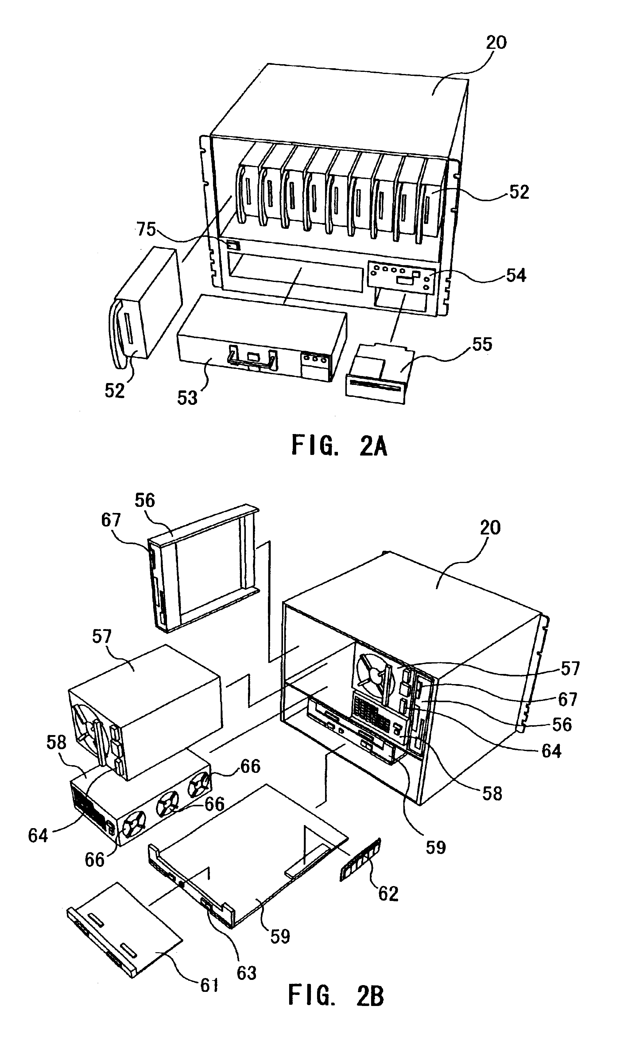
[0023]One aspect of the present invention is a method of controlling a storage apparatus. The storage apparatus includes: at least one housing A in which a storage device and a controller are provided; at least one housing B in which a storage device and a peripheral device are provided; and a transmission path for connecting the storage device and the controller of the housing A, and the storage device of the housing B to enable communication therebetween. The method comprises: controlling operation of the storage device of the housing B according to an operating state of the storage device of the housing A through communication via the transmission path; and controlling operation of the peripheral device according ...


PUM


Abstract

A storage apparatus comprises at least one housing A in which a storage device and a controller are provided, at least one housing B in which a storage device and a peripheral device are provided, and a transmission path for connecting the storage device and the controller of the housing A, and the storage device of the housing B to enable communication therebetween. The storage apparatus is capable of controlling operation of the storage device of the housing B according to an operating state of the storage device of the housing A through communication via the transmission path; and controlling operation of the peripheral device according to an operating state of the storage device of the housing B.

Description

CROSS-REFERENCE TO RELATED APPLICATIONS[0001]The present application claims priority upon Japanese Patent Application No. 2002-174948 filed Jun. 14, 2002, which is herein incorporated by reference.BACKGROUND OF THE INVENTION[0002]1. Field of the Invention[0003]The present invention relates to a storage apparatus and a control method therefor.[0004]2. Description of the Related Art[0005]There are known disk array devices that have a configuration in which housings, each of which accommodating a plurality of disk drives, are mounted in several layers. Such disk array devices are called “rackmount” disk array devices. Japanese Patent Application Laid-open Publication No. 2001-339853 discloses a power supply method for such a type of disk array device. According to the method disclosed, a power-supply apparatus is provided outside the housing and connected to a basic housing and an extension housing by dedicated control lines for controlling power supplied to the housings in such a way ...

Claims


Application Information

Patent Timeline
IPC IPC(8): G06F1/32G06F1/20G06F1/18G11B33/14
CPCG06F1/184G06F1/187G06F1/20G06F1/203G06F1/206G06F1/3221G06F3/0625G06F3/0634G06F3/0658G06F3/0689G11B33/126G11B33/142G11B33/144Y02B60/1246Y02B60/1275Y02D10/00
Inventor SUZUKI, KATSUYOSHIKANO, AZUMA
Owner HITACHI LTD
Learn More