Compression latch

Inactive Publication Date: 2005-10-11
SOUTHCO
View PDF19 Cites 65 Cited by
  • Summary
  • Abstract
  • Description
  • Claims
  • Application Information

AI Technical Summary

Problems solved by technology

The compression latch of U.S. Pat. No. 4,763,935 does not provide for a hand

Method used


Image

  • Compression latch
  • Compression latch
  • Compression latch

Examples


Embodiment Construction

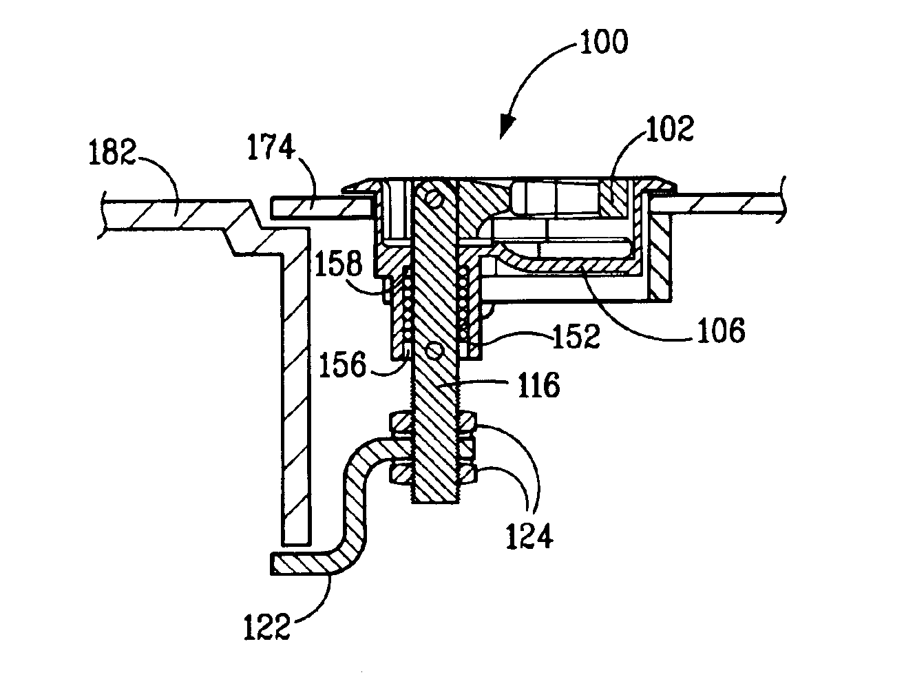
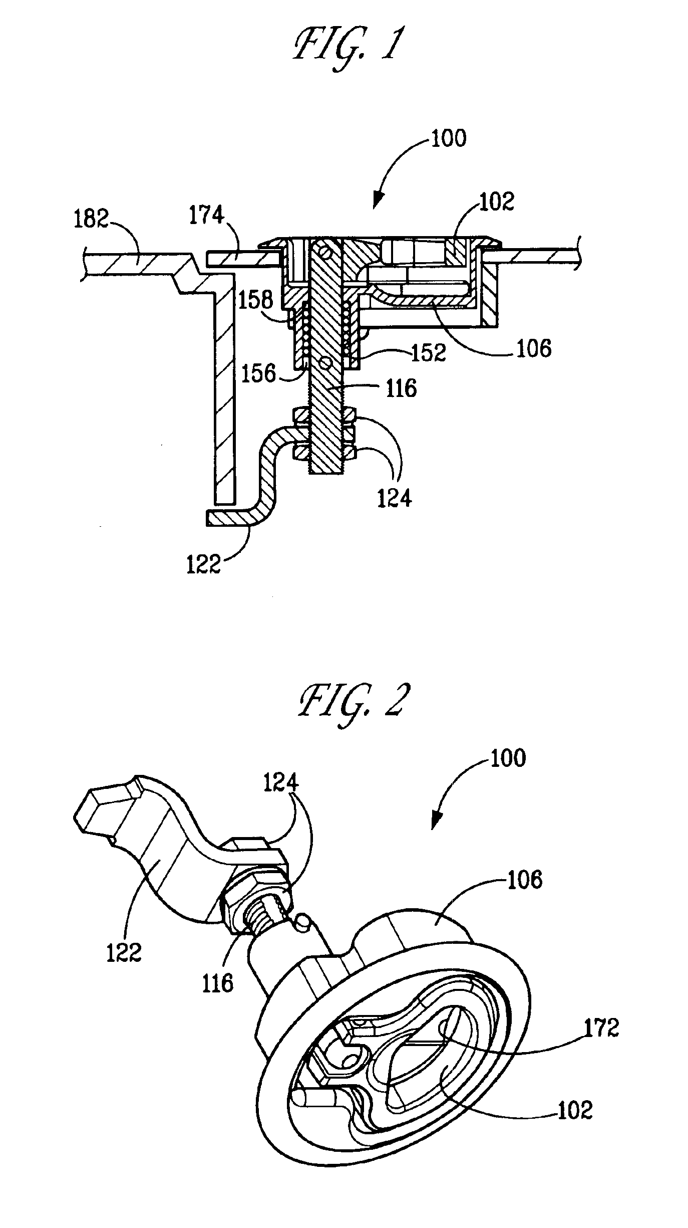
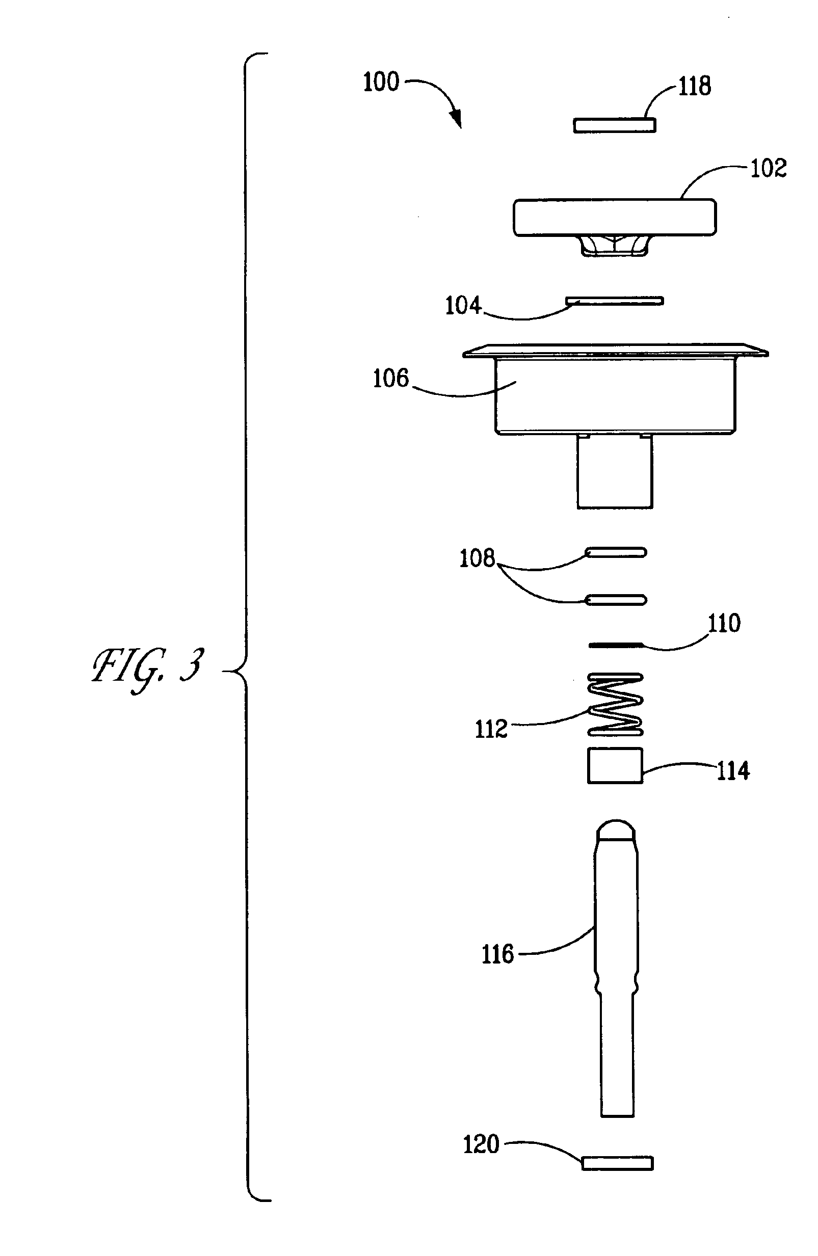
[0029]The present invention is directed to a latch for selectively maintaining a first member in a closed position relative to a second member. The first member, for example, may be a door and the second member, for example, may be a doorframe or a keeper attached to the doorframe. The latch of the present invention in general comprises a housing adapted for mounting to the first member; a pivotal handle supported relative to the housing such that the handle can be folded down relative to the housing; a pawl; and means for moving the pawl in a combination of rotational and linear translational movements responsive to at least some movements of the handle. The latch pawl is movable between a latched position and an unlatched position and the handle can be folded down when the rotational position of the pawl corresponds to both the latched and unlatched positions. By appropriate movement of the handle, the pawl can be rotated to bring the pawl into position behind a portion of the doo...


PUM


Abstract

A compression latch with a folding handle for selectively holding a door closed. The latch includes a housing with a cup portion for receiving the handle in the folded down position such that the projection of the latch handle above the exterior surface of the door is minimized in the folded-down position. The handle functions to move a pawl in a combination of rotational and linear translational movements as the pawl is moved between latched and unlatched positions.

Description

BACKGROUND OF THE INVENTION[0001]1. Field of Invention[0002]The present invention relates to a compression latch for selectively maintaining a panel or door in a closed position relative to a doorframe or the like.[0003]2. Brief Description of the Related Art[0004]In many applications the need arises to selectively maintain a panel or door in a closed position relative to a doorframe or the like, while developing a compressive force between the door or panel and the doorframe. For example, when a gasket is used to provide a seal between a door and a doorframe when the door is closed, it would be desirable for the latch holding the door closed to provide a compressive force to compress the gasket between the door and the doorframe to effectively seal the any gap or seam between the door and doorframe. Latches that develop this type of compressive force between the door and doorframe are known as compression latches. An example of a known compression latch can be seen in U.S. Pat. No....

Claims


Application Information

Patent Timeline
IPC IPC(8): E05B17/00E05C5/00E05C5/02E05B1/00
CPCE05B17/0025E05C5/02E05B1/0092Y10T16/458Y10S292/31Y10T292/1048Y10T292/089Y10T292/0893Y10T292/0932Y10T292/0949Y10T292/108Y10T292/57
Inventor JACKSON, JR., JOSEPH W.CLISHAM, GERARD J.GODIN, JEREMY L.RIBLETT, H. ALLEN
Owner SOUTHCO
Why Eureka
Try Eureka