Compact multi-stage condenser dump device

a dump device and multi-stage technology, applied in steam/vapor condensers, steam engine plants, lighting and heating apparatuses, etc., can solve the problems of high noise levels at the acc duct surface that can generate unacceptable noise levels, plant operations with extensive noise levels may face financial penalties, and achieves reduced noise and vibration, minimizes projection, and reduces noise and vibration.

Active Publication Date: 2020-08-04
CONTROL COMPONENTS INC
View PDF18 Cites 0 Cited by
  • Summary
  • Abstract
  • Description
  • Claims
  • Application Information

AI Technical Summary

Benefits of technology

[0012]The dump device is adapted to replace current two-stage dump devices and their Bell housings for ACC condensers, and generally comprises a compact, torispherical drilled-hole device which mounts on the surface of the duct. In this regard, the dump device provides a compact and lightweight method for discharging steam into the duct. The dump device has a large surface area which minimizes noise and vibration, and further has a low-profile shape which minimizes projection into the duct and flow disturbance therein.
[0013]In greater detail, in an exemplary embodiment, the dump device generally comprises two torispherical heads which are adapted to be installed directly at the condenser duct. The torispherical shapes provide a large face area, which allows for drilling holes on the face of each of these heads in sizes, shapes, patterns and arrangements as needed to satisfy and one of a multiplicity of different capacity requirements for the purpose of dumping steam to the ACC condenser. In this regard, the hole-pattern distribution on the first and second stages has an important impact on noise performance. Along these lines, the first stage and / or second stage may feature a blank area in the center. The blank area(s) can be used to prevent direct line of sight flow from the first stage to and through the second stage for the purposes of: (1) preventing jet recombination; and (2) lowering reaction forces. The holes are preferably drilled perpendicular to the curved surfaces of the first and second stages of the dump device. This diffuses the jets, improves distribution of energy into the duct, and minimizes noise, vibration, and reaction loads (lower load in the same plane).
[0014]Since pressure distribution between stages also has an important impact on performance, the dump device may be configured to have a Mach number less than 1 (e.g., preferably subsonic) at the first stage to reduce or eliminate noise or shock wave problems where the steam is inside the dump device, with the outer or second stage having a Mach more than 1 for space limitation. In this regard, the second stage is designed to limit average velocity across the surface of the dump device to an acceptable limit during normal and trip conditions. The limits will typically be around 0.5 Mach during normal operating conditions, and around transonic during trip. The velocity limit during normal operation is selected to reduce noise. The velocity limit during trip is selected to prevent excessive reaction loads.

Problems solved by technology

High noise levels at the ACC duct surface can generate unacceptable noise levels at the plant boundary and in neighboring communities.
This problem is especially important in combined cycle power stations.
With many combined cycle plants on a daily cycling, start-up noise can become a severe constraint in plant operation.
Plants with extensive noise levels may face financial penalties, and in some cases, suspension of plant operation.
Due to the large size of the ACC duct, traditional noise treatment methods like acoustic enclosures or insulation are impractical or insufficient.
However, these designs can generate noise levels in excess of 130 dBA at a distance of 1 m from the ACC duct surface.
The large amount of concentrated sound power creates vibration that can cause cracks in the duct walls and dump element mounting ring.
To meet the required capacity, these two-stage dump tubes become so big that they block a considerable portion of the cross-section of the condenser duct.
This blockage is undesirable, as it increases condenser pressure and consequently decreases plant efficiency since, i.e., dump tubes which project into the duct block flow and create backpressure on the dump tube.
The requirement for Bell housing is seen for most of the hot reheat (HRH) steam bypass to ACC condensers, where noise limitation is a concern.
However, the Bell housings are relatively big, costly, and noisy.

Method used


Image

  • Compact multi-stage condenser dump device
  • Compact multi-stage condenser dump device
  • Compact multi-stage condenser dump device

Examples


first embodiment

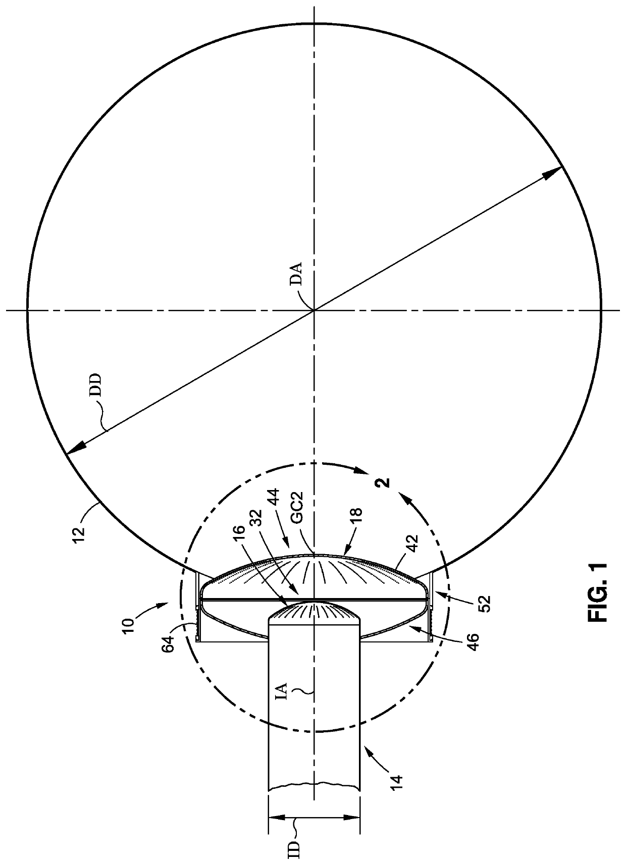
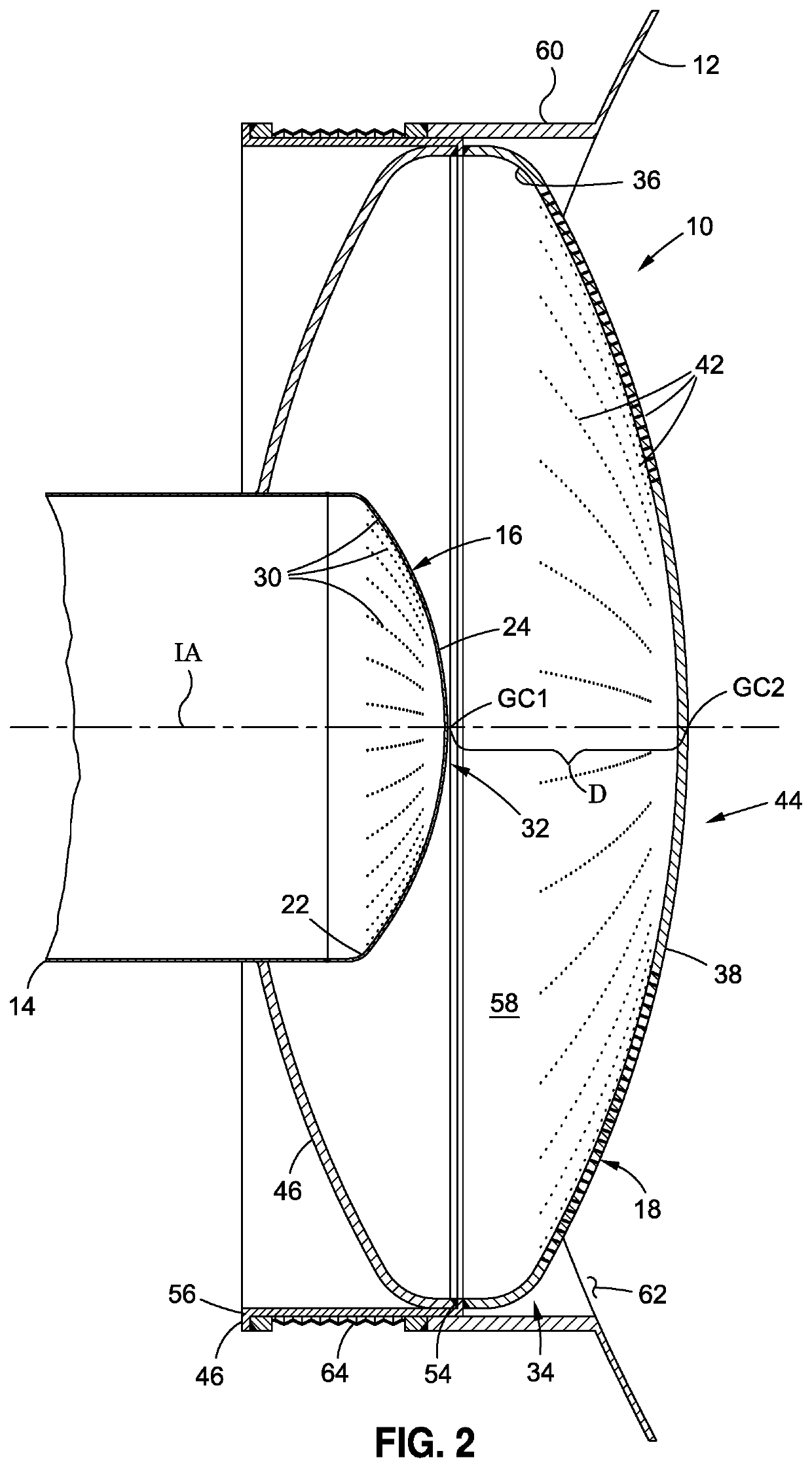
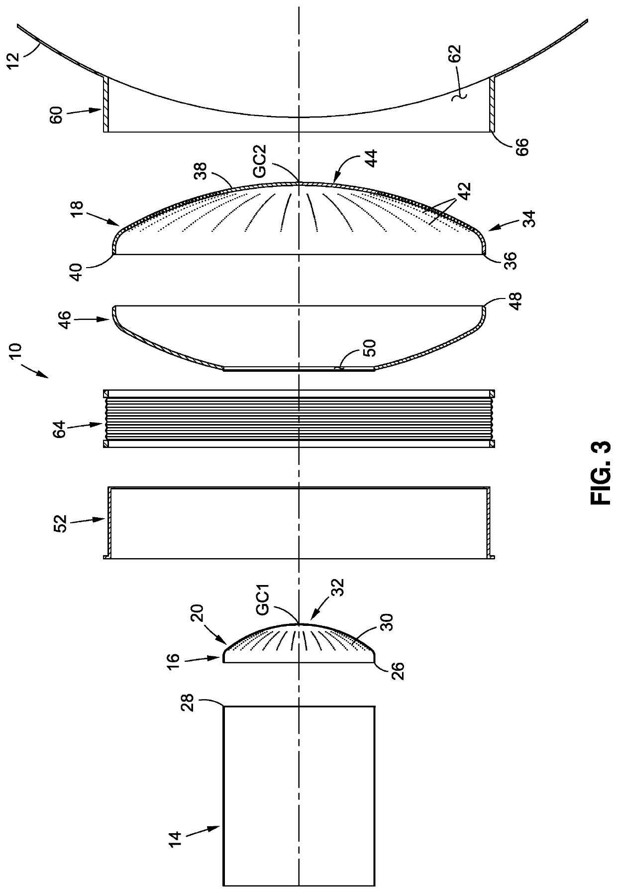
[0037]Referring now to the drawings wherein the showings are for purposes of illustrating preferred embodiments of the present disclosure only, and not for purposes of limiting the same, FIGS. 1-4 depict a dump device 10 constructed in accordance with the present disclosure. The dump device 10 is particularly suited for operative integration between and mounting to a dump tube or duct 12 (e.g., an air cooled condenser duct) and a corresponding steam inlet pipe 14 as allows the dump device 10 to facilitate the discharge of steam from the steam inlet pipe 14 into the duct 12. As seen in FIG. 1, the duct 12 will typically be cylindrically configured, having a generally circular cross-sectional configuration and defining a duct axis DA, while further being provided with an inner duct diameter DD in the range of about 16 to 24 feet. Similarly, the steam inlet pipe 14 will typically be cylindrically configured, having a generally circular cross-sectional configuration and defining an inle...

second embodiment

[0062]Referring now to FIGS. 9, 10 and 11, there is shown a dump device 110 constructed in accordance with the present disclosure. Many of the structural and functional features of the dump device 110 are the same as those described above in relation to the dump device 10. Thus, only the structural distinctions between the dump devices 10, 110, and the distinctions between the ancillary structures used to facilitate the cooperative engagement thereof to the duct 12, will be described in more detail below with specific reference to FIGS. 9-11.

[0063]In greater detail, one of the primary distinctions between the dump devices 10, 110 lies in the first stage 116 of the dump device 110 comprising a portion of the steam inlet pipe 14 in combination with the first head 120 which is attached to the distal end of the steam inlet pipe 14 defined by the distal rim 28 thereof. In the dump device 110, the first head 120 of the first stage 116 is, like the above-described first stage 20 of the dum...

third embodiment

[0067]Referring now to FIGS. 12 and 13, there is provided generally schematic depictions of a dump device 210 constructed in accordance with the present disclosure. Whereas the dump devices 10, 110 are each generally two-stage versions, the dump device 210 is a three-stage version essentially comprising a meld of various structural features of the dump devices 10, 110, and the arrangements shown in FIGS. 1-3 and 9-11, as elaborated upon in more detail below.

[0068]In general terms, the dump device 210, from a starting structural standpoint, largely mimics the structural and functional features of the dump device 10 and those structural features used to facilitate its cooperative engagement to both the steam inlet pipe 14 and duct 12. However, for purposes of the description below, what is described as the second stage 18 above in the dump device 10 is characterized as the third stage 18′ in the dump device 210, though the second stage 18 and third stage 18′ are, in large measure, str...


PUM


Abstract

A multi-stage, torispherical drilled-hole dump device which mounts on the surface of an air cooled condenser (ACC) duct, and provides a compact and lightweight method for discharging steam into the duct by presenting a large surface area which minimizes noise and vibration, while also having a low-profile shape which minimizes projection into the duct and flow disturbance in the duct.

Description

CROSS-REFERENCE TO RELATED APPLICATIONS[0001]The present application claims priority to U.S. Provisional Application Ser. No. 62 / 452,849 entitled COMPACT MULTI-STAGE CONDENSER DUMP DEVICE filed Jan. 31, 2017.STATEMENT RE: FEDERALLY SPONSORED RESEARCH / DEVELOPMENT[0002]Not ApplicableBACKGROUND1. Technical Field[0003]The present disclosure relates generally to noise attenuation devices and, more particularly, to a multi-stage (e.g., two-stage), torispherical drilled-hole dump device which mounts on the surface of an air cooled condenser (ACC) duct, and provides a compact and lightweight method for discharging steam into the duct by presenting a large surface area which minimizes noise and vibration, while also having a low-profile shape which minimizes projection into the duct and flow disturbance in the duct.2. Description of the Related Art[0004]In a power plant with an air cooled condenser (ACC), steam is carried from the steam turbine exhaust to the condenser via a large, thin, wal...

Claims


Application Information

Patent Timeline
Patent Type & Authority Patents(United States)
IPC IPC(8): F01K9/00F28B1/06F28F9/02F28B9/02
CPCF01K9/003F28B9/02F28B1/06F28F9/0278F28F9/028F28F2265/28
Inventor MOUSAVI, POOPAK
Owner CONTROL COMPONENTS INC
Why Eureka
Try Eureka