
V-type engine and motorcycle incorporating same

a v-type engine and v-type technology, applied in the direction of machines/engines, non-mechanical valves, jet propulsion mountings, etc., can solve the problems of relatively long and complicated oil passage from the hydraulic controller to the valve rest mechanism, and achieve the effect of simplifying the structure of the oil passag

Inactive Publication Date: 2011-05-24
HONDA MOTOR CO LTD
View PDF12 Cites 0 Cited by
  • Summary
  • Abstract
  • Description
  • Claims
  • Application Information

AI Technical Summary

Benefits of technology

[0006]The present invention has been made in view of the above situation, and it is an object hereof to provide a vehicle V-type engine in which the oil passage from the hydraulic controller to the hydraulic valve rest mechanism is shortened, and to thereby simplify the structure of the oil passage.
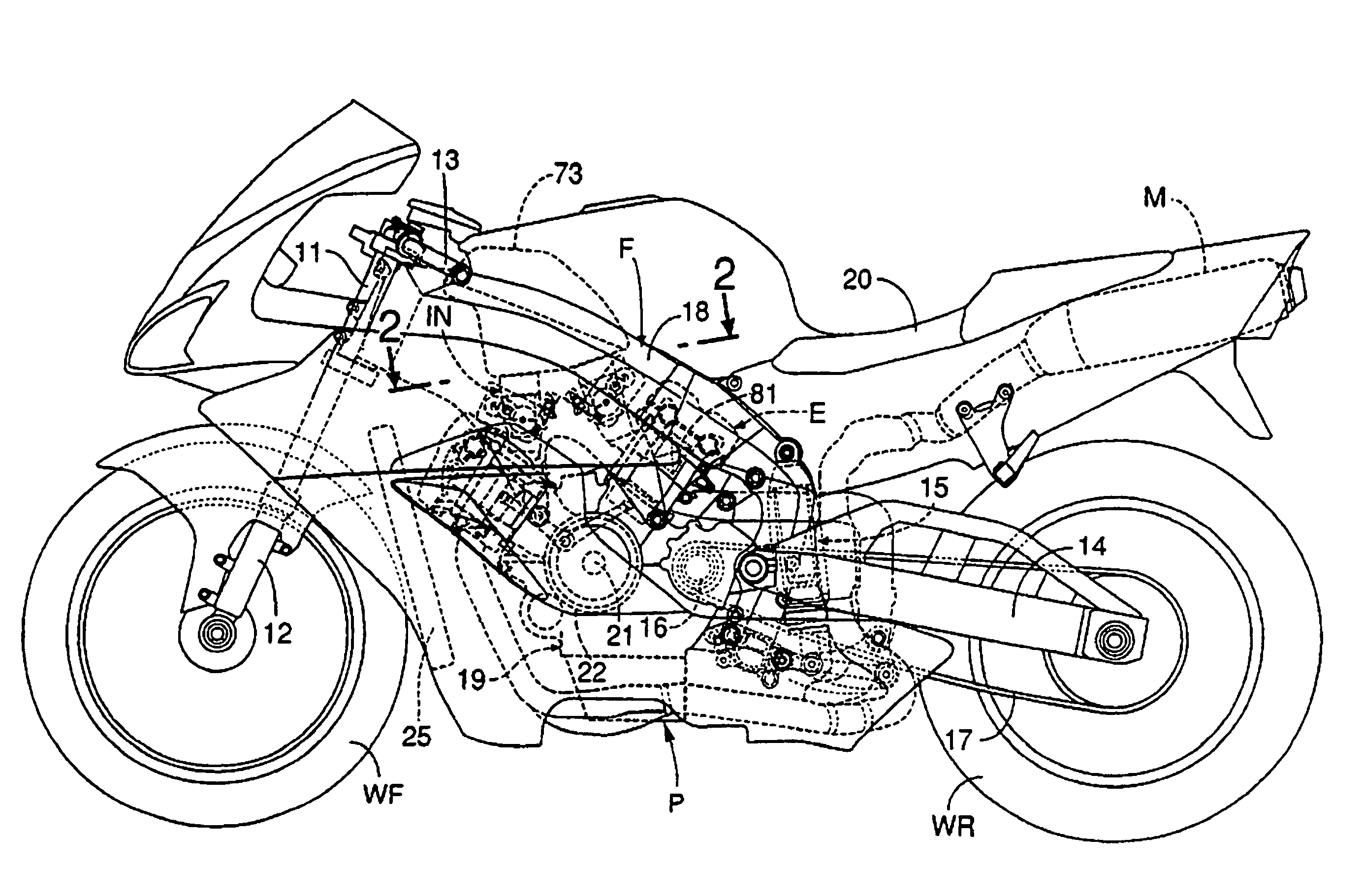
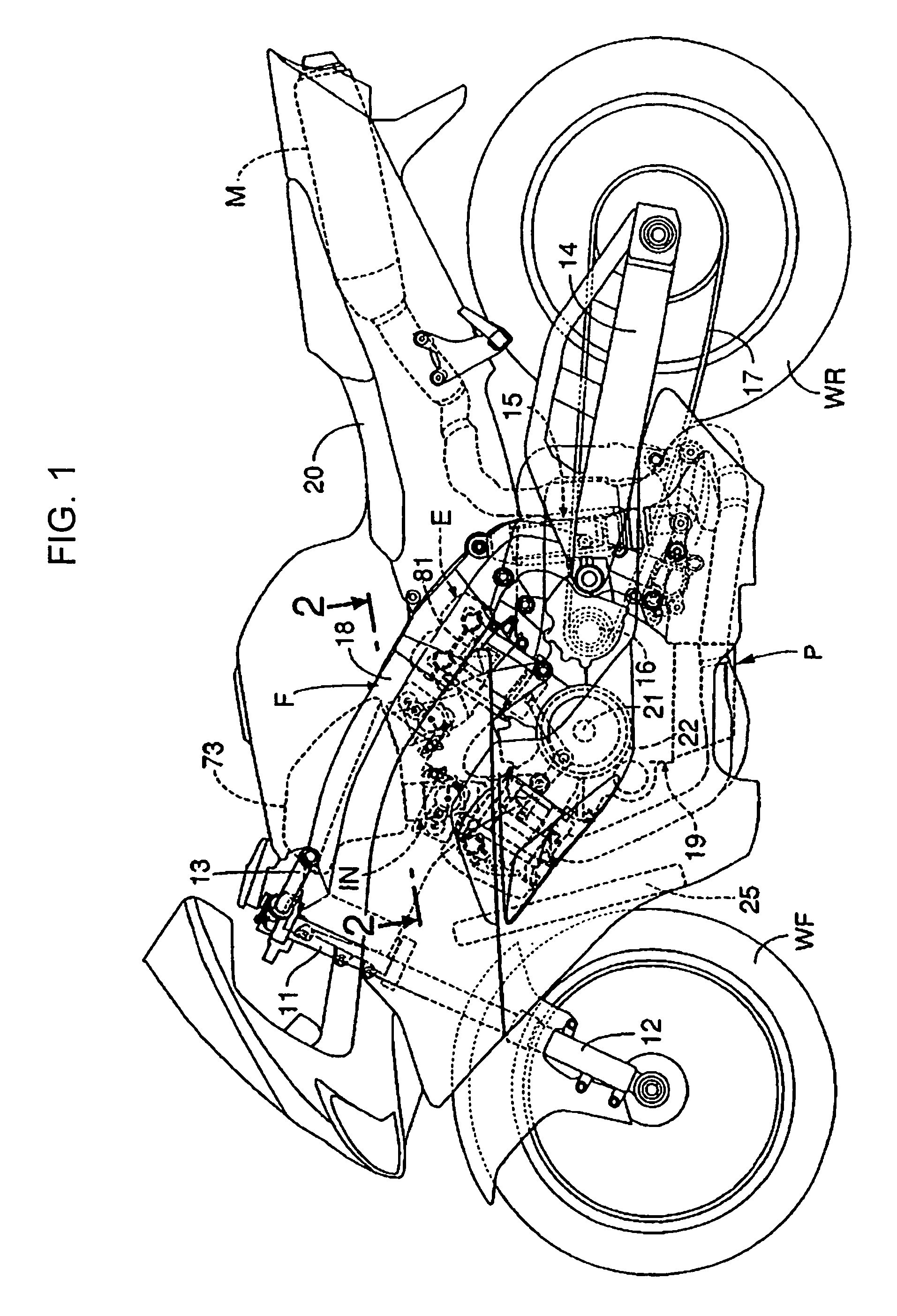
[0011]In a first aspect of the invention, the hydraulic controller that controls the hydraulic pressure supplied to the hydraulic valve rest mechanism which is provided in the valve actuation unit accommodated in the valve chamber between the cylinder heads and the head covers, is attached to the cylinder head in which the valve rest mechanism is situated. Because the hydraulic controller is provided near the valve rest mechanism, the oil passage from the hydraulic controller to the valve rest mechanism can be shortened, and the oil passage structure can be simplified. Further, as the hydraulic controller is provided on at least one of the side surfaces of the cylinder heads along the axis line of the crankshaft, the hydraulic controller does not significantly restrict the arrangement of intake pipes and exhaust pipes connected to the cylinder heads.
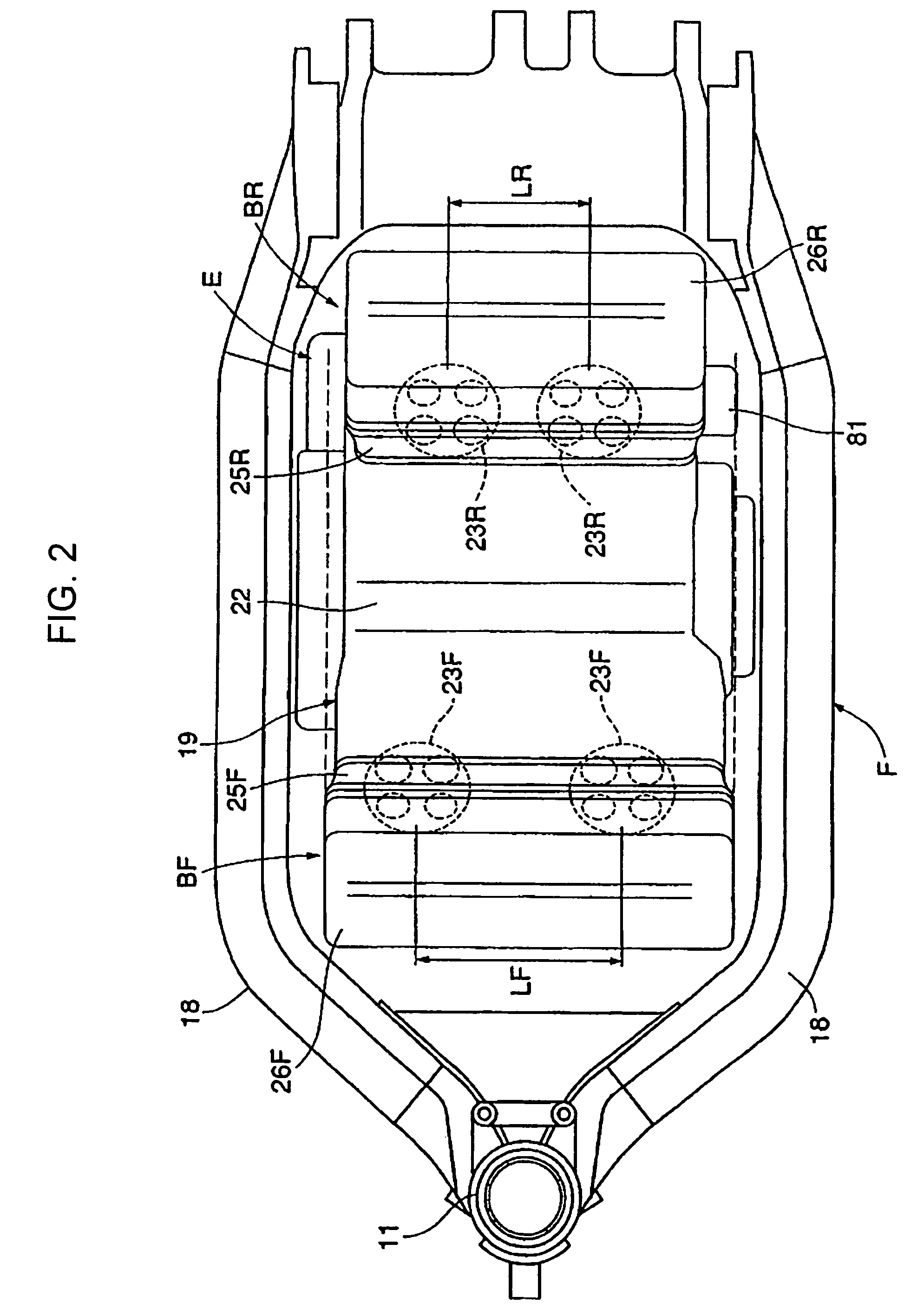
[0012]A second aspect of the invention permits a sideways projection of the hydraulic controller from the engine to be minimized, and therefore, the hydraulic controller is protected in a simple manner. Further, in the second aspect hereof, the hydraulic controller is provided in the cylinder head in the rear bank, with its width in the vehicle width direction smaller than that of the front bank, so as to be hidden behind the front bank, in a front view. Even when the invention is applied to a saddle-type vehicle in which a operator's seat is provided in a position toward the rear of and adjacent to a rear bank, because the hydraulic controller is provided on the side surface of the cylinder head, the influence of the hydraulic controller on a vehicle operator's straddling position can be limited. Further, in another aspect hereof, the hydraulic controller is protected by the main frames, thereby eliminating the requirement for a specialized protection member, and therefore the total number of necessary parts can be reduced.

Problems solved by technology

Accordingly, the oil passage from the hydraulic controller to the valve rest mechanism is relatively long and complicated.

Method used


Image

  • V-type engine and motorcycle incorporating same
  • V-type engine and motorcycle incorporating same
  • V-type engine and motorcycle incorporating same

Examples


first embodiment

[0069]Next, an operation of the first embodiment will be described. The first valve actuation unit 36 having a double overhead camshaft structure, in which the intake-side and exhaust-side camshafts 38, 39 individually correspond to the intake valves 33R and the exhaust valves 34R, is accommodated in the valve chamber 35R in the rear bank BR out of the front bank BF and the rear bank BR of the V-shaped main engine body 19. The second valve actuation unit 37 having the common single camshaft 42 for the intake valves 33F and the exhaust valves 34F is accommodated in the valve chamber 35F in the front bank BF.

[0070]Accordingly, in the front bank BF on the side where the second valve actuation unit 37 is provided, the cylinder head 25F and the head cover 26F can be downsized. In comparison with a case where the valve actuation units in the front bank BF and the rear bank BR are both have the double overhead camshaft structure, the longitudinal length of the main engine body 19 can be sh...

second embodiment

[0076]FIG. 10 shows the present invention. A V-type structured main engine body 19′ of an engine E′ has a front bank BF′ having a cylinder head 25F′ and a head cover 26F′, and a rear bank BR′ having a cylinder head 25R′ and a head cover 26R′. The front bank BF′ and the rear bank BR′ are mutually shifted in the vehicle width direction.

[0077]Further, the hydraulic controller 81 is provided on the side surface of both end side surfaces of the front bank BF′ along the axis line of the crankshaft 21 (first embodiment), provided inside from the side surface in the outermost position in the vehicle width direction, i.e., on the left side surface of the cylinder head 25R′ in the second embodiment.

[0078]According to the second embodiment, wide projection of the hydraulic controller 81 from the entire width of the engine can be reduced, and protection of the hydraulic controller 81 can be facilitated.


PUM


Abstract

In a V-type engine for a vehicle, in which a hydraulic valve rest mechanism which selectively holds at least one of an intake valve and an exhaust valve corresponding to a part of plural cylinders in a valve-closed rest state in correspondence with a vehicle running status is provided in a valve actuation unit, and a hydraulic controller which controls hydraulic pressure of the valve rest mechanism is provided in a main engine body, to reduce the distance of oil passage from the hydraulic controller to the hydraulic valve rest mechanism and simplify the structure of the oil passage. A hydraulic controller is provided on at least one side surface of a cylinder head, and may be generally oriented along a line which is substantially parallel to a central axis of a cylinder bore.

Description

CROSS-REFERENCE TO RELATED APPLICATIONS[0001]The present invention claims priority under 35 USC §119 based on Japanese patent application 2007-095690, filed on Mar. 30, 2007. The entire disclosure of this priority document, including specification, claims, and drawings, is incorporated by reference herein.BACKGROUND OF THE INVENTION[0002]1. Technical Field of the Invention[0003]The present invention relates to a V-type engine, in which intake and exhaust valves are provided in cylinder heads of a front bank and a rear bank cooperating to form a V shape extending in a longitudinal direction of a vehicle, and also to a motorcycle incorporating the engine. More particularly, present invention relates to a V-type engine incorporating a hydraulic valve rest mechanism, that is operable to selectively and temporarily hold one or more of the valves in a valve-closed resting state according to a vehicle running status. The valve rest mechanism is provided in a valve actuation unit, disposed ...

Claims


Application Information

Patent Timeline
Patent Type & Authority Patents(United States)
IPC IPC(8): F01L1/34
CPCF01L13/0005F02B75/22F02B61/02F01L2001/34433
Inventor MAEHARA, HAYATOSAITO, SHINJITSUKUI, TAKAAKI
Owner HONDA MOTOR CO LTD
Learn More