Eureka AIR delivers breakthrough ideas for toughest innovation challenges, trusted by R&D personnel around the world.

Terminal fitting with seal protecting features

Active Publication Date: 2005-10-11
SUMITOMO WIRING SYST LTD
View PDF8 Cites 19 Cited by
  • Summary
  • Abstract
  • Description
  • Claims
  • Application Information

AI Technical Summary

Benefits of technology

[0008]The seal is squeezed when the fastening piece is crimped into connection with the seal and the wire, and the fastening piece strongly presses the outer surface of the seal. However, the seal protecting portion is formed at the corner of the contact surface and is aligned at an obtuse angle to the contact surface of the fastening piece. Thus, the fastening piece will not bite into the seal and there is no possibility of cracking the seal.

Problems solved by technology

The inner side edges of the fastening pieces of the prior art terminal fitting may bite into the outer surface of the sealing member and may crack the fastened portion of the sealing member.

Method used


Image

  • Terminal fitting with seal protecting features
  • Terminal fitting with seal protecting features
  • Terminal fitting with seal protecting features

Examples


Embodiment Construction

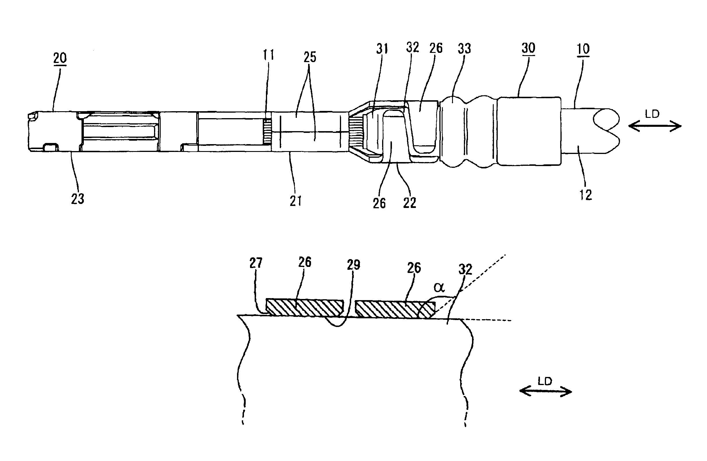
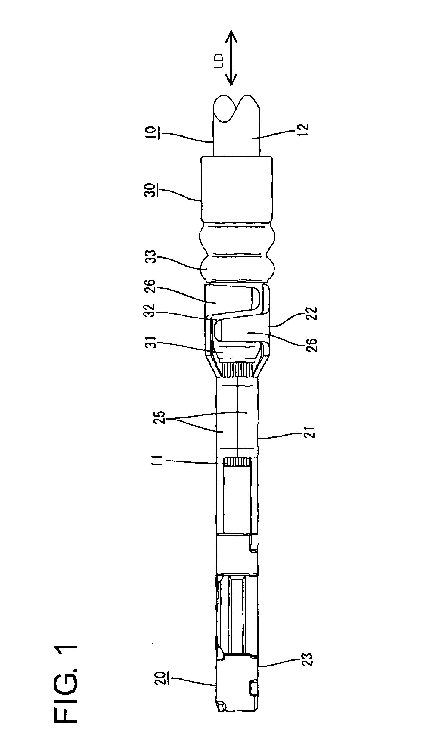
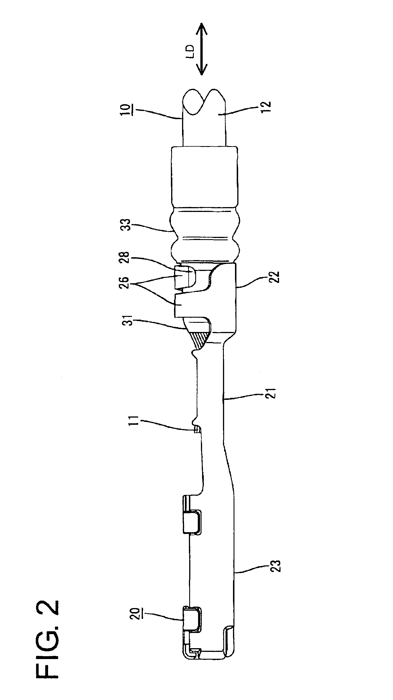
[0022]A female terminal fitting according to the invention is identified by the numeral 20 in FIGS. 1 to 7. The female terminal fitting 20 is to be connected with a wire 10 having a seal 30 fit thereon.

[0023]The wire 10 includes a core 11 preferably made of a plurality of fine metal strands and an insulation coating 12 that covers the core 11, as shown in FIG. 1. The core 11 is exposed along a specified length by having the insulation coating 12 stripped at an end portion. In the following description, a side of the wire 10 where the core 11 is exposed and a side thereof covered by the insulation coating 12 are referred to as front and rear sides with respect to the longitudinal direction LD of the wire 10.

[0024]The seal 30 is formed of a sealing material, and preferably a rubber material such as a silicon rubber. The seal 30 has a tubular shape, and is dimensioned to be fit and resiliently held in surface contact on the outer circumferential surface of the insulation coating 12 of ...


PUM


Abstract

A female terminal fitting (20) is provided with a pair of fastening pieces (26) extending from the opposite side edges of a bottom plate (24), and the fastening pieces (26) are bent inward toward each other, thereby wrapping around the outer circumferential surface of a sealing member (30) fitted on a wire (10) to fasten the sealing member (30) together with the wire (10). Sealing-member protecting portions (27) are formed on side edges of the inner surfaces of the fastening pieces (26) and are aligned at obtuse angles to contact surfaces (29). Therefore, the bite in the sealing member (30) can be hindered over a wide range.

Description

BACKGROUND OF THE INVENTION[0001]1. Field of the Invention[0002]The invention relates to a terminal fitting to be crimped into connection with both a sealing member and a wire.[0003]2. Description of the Related Art[0004]Japanese Unexamined Patent Publication No. 2002-203636 discloses a terminal fitting for use in a watertight connector. The terminal fitting has a wire barrel for crimped connection with a core of a wire and an insulation barrel for crimped connection with a sealing member. Fastening pieces extend from opposite side edges of a bottom plate of the insulation barrel. The respective fastening pieces are bent in towards each other and are crimped around the outer circumferential surface of the sealing member.[0005]The inner side edges of the fastening pieces of the prior art terminal fitting may bite into the outer surface of the sealing member and may crack the fastened portion of the sealing member.[0006]The present invention was developed in view of the above problem ...

Claims


Application Information

Patent Timeline
IPC IPC(8): H01R4/18H01R13/52H01R4/10
CPCH01R4/185H01R13/5205
Inventor TABATA, MASAAKIIMAI, YUUJIROU
Owner SUMITOMO WIRING SYST LTD
Why Eureka
Eureka Blog
Learn More