Method and apparatus for measuring flow rate through and polishing a workpiece orifice

a flow rate and workpiece technology, applied in the direction of liquid/fluent solid measurement, manufacturing tools, instruments, etc., can solve the problems of affecting the overall manufacturing process of the method using flow meters, affecting the quality of the workpiece, and requiring long measurement times

Inactive Publication Date: 2005-10-11
EXTRUDE HONE CORP
View PDF5 Cites 13 Cited by
  • Summary
  • Abstract
  • Description
  • Claims
  • Application Information

AI Technical Summary

Problems solved by technology

However, methods using flow meters often create bottlenecks in the overall manufacturing process due to lengthy measurement times. Since the usual measurement method is to measure the flow rate through a part at a given pressure, then depending on the means of supplying pressurized calibration fluid to the part, it may take several seconds to achieve a desired pressure and then to stabilize the fluid flow at that pressure, at which time flow measurements may be taken.
Moreover, the flow measurement devices often require long measurement times to deliver a stable measurement.
If rework is not possible, the part would be scrapped.

Method used


Image

  • Method and apparatus for measuring flow rate through and polishing a workpiece orifice
  • Method and apparatus for measuring flow rate through and polishing a workpiece orifice
  • Method and apparatus for measuring flow rate through and polishing a workpiece orifice

Examples


Embodiment Construction

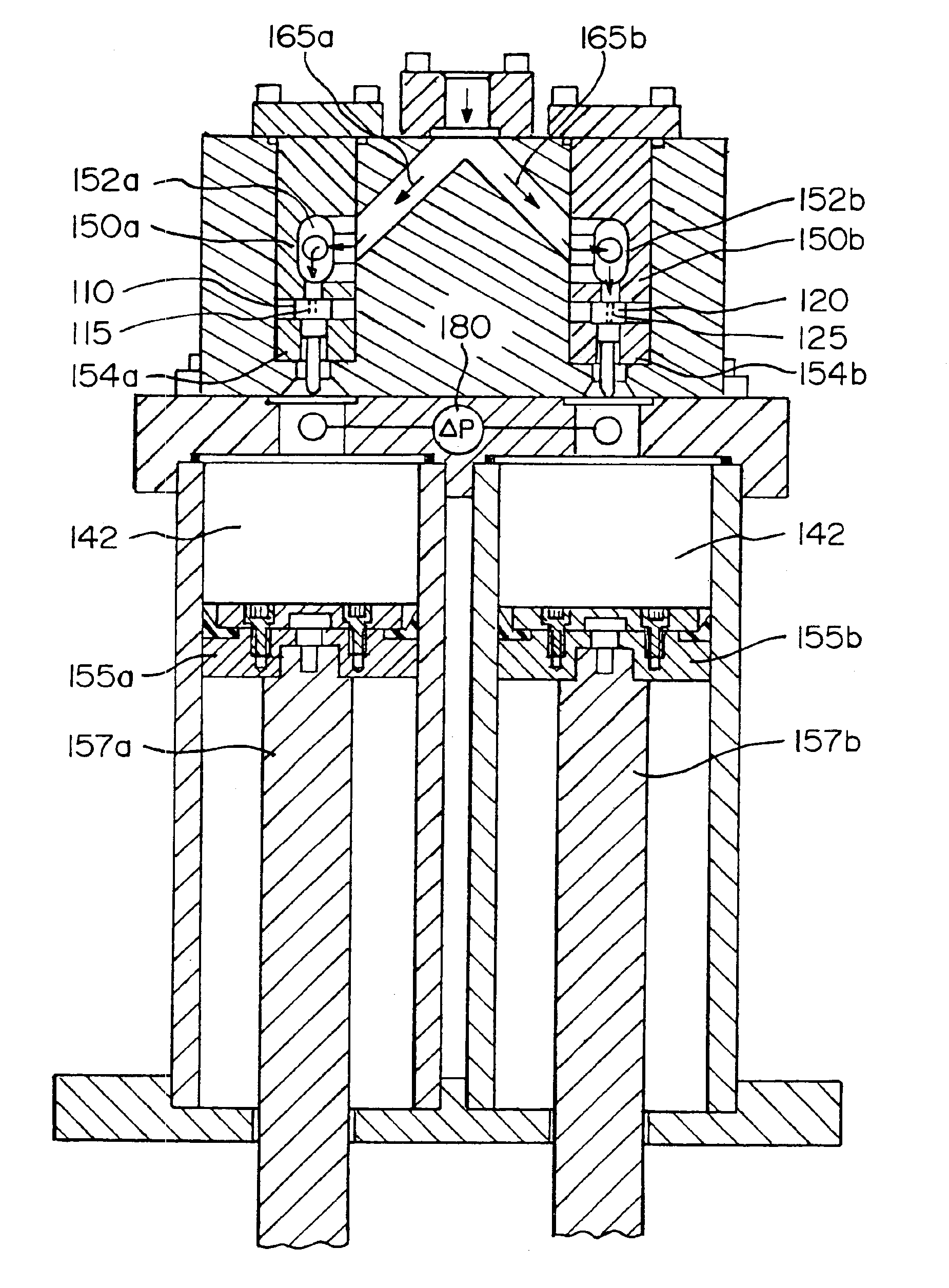
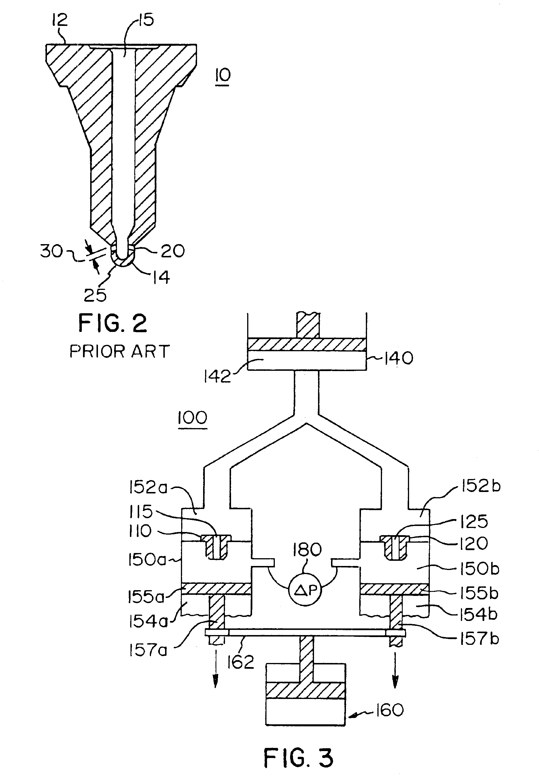
[0024]The flow rate through an orifice is a function of the pressure drop across the orifice, the geometry of the orifice, and the properties of the fluid flowing through the orifice. In general, a fluid under uniform pressure will pass through two orifices that have identical geometries at the same flow rate, whether mass flow rate or volumetric flow rate. In the same way, if fluid under uniform upstream pressure passes through each of these two identical orifices, the pressure drop past the orifices will be identical.

[0025]A typical workpiece may be a nozzle having a plurality of radially oriented orifices to disperse fluid travelling therethrough. A typical workpiece may also be a nozzle having a single orifice. A typical workpiece may also be an orifice plate made up of a simple flat plate having a single orifice extending therethrough. For purposes of discussion herein, the workpiece and the associated master part will have a single orifice with the understanding that each the ...


PUM

PropertyMeasurementUnit
pressureaaaaaaaaaa
timeaaaaaaaaaa
diameteraaaaaaaaaa

Abstract

A method and apparatus for comparing the flow rate through an orifice within a master part with the orifice within a workpiece by subjecting each orifice to an identical fluid at an identical temperature, under an identical pressure, and comparing the downstream pressures of the fluid exiting these orifices when the upstream pressure is constant or comparing the upstream pressure when the downstream pressure is constant. For purely measurement purposes, the fluid may be a non-abrasive media, however, in the event the workpiece orifice must be machined, it is possible to introduce a flowable abrasive media, and pass this media through the orifices until the desired pressure difference is achieved. With additional flow characteristics of the master part, it is also possible to calculate the flow rate through the workpiece orifice using only the pressure differential at the exits of the workpiece and the master part.

Description

[0001]This application is a CIP of Ser. No. 10 / 668,590 filed Sep. 23, 2003 now abandoned.BACKGROUND OF THE INVENTION[0002]1. Field of the Invention[0003]The invention relates to a method and apparatus for determining whether or not the flow rate through one or more orifices in a workpiece are within permissible tolerance when compared to the flow rate through one or more matching orifices in a master part. This determination is based upon characteristics of fluid flow passing through the orifices in the workpiece and in the master part. Additionally, the subject invention is directed to a method and apparatus for machining the one or more orifices in a workpiece so that the geometry better conforms to the geometry of the matching one or more orifices of the master part. Finally, the invention relates to a method of determining the flow rate through the one or more orifices of the workpiece.[0004]2. Description of Related Art[0005]Components such as fuel injectors and orifice plates ...

Claims


Application Information

Patent Timeline
Patent Type & Authority Patents(United States)
IPC IPC(8): B24B1/00B24B15/00B24B19/00B24B7/20B24B7/00B24B7/19B24B7/30G01F7/00G01F
CPCB24B31/116
Inventor GREENSLET, JOHN M.RHOADES, LAWRENCE J.
Owner EXTRUDE HONE CORP
Why Eureka
Try Eureka