Pipette tip with an internal sleeve and method for forming same

a technology of pipette tip and internal sleeve, which is applied in the direction of manufacturing tools, laboratory glassware, instruments, etc., can solve the problems of fatigue and even injury, difficult removal of the tip, and considerable for

Inactive Publication Date: 2005-10-18
QUALITY SCI PLASTICS
View PDF9 Cites 37 Cited by
  • Summary
  • Abstract
  • Description
  • Claims
  • Application Information

AI Technical Summary

Problems solved by technology

In some instances this force can be considerable.
Removal of the tip can be difficult as well, and over many uses during a day, can cause fatigue and even injury over time.

Method used


Image

  • Pipette tip with an internal sleeve and method for forming same
  • Pipette tip with an internal sleeve and method for forming same
  • Pipette tip with an internal sleeve and method for forming same

Examples


Embodiment Construction

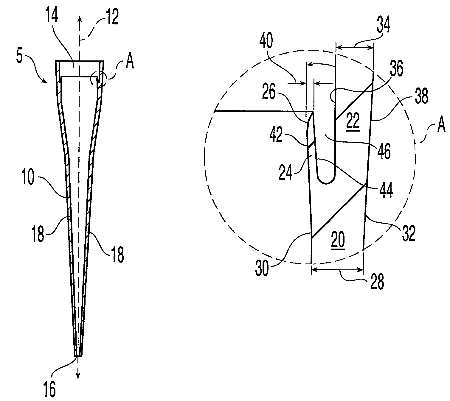
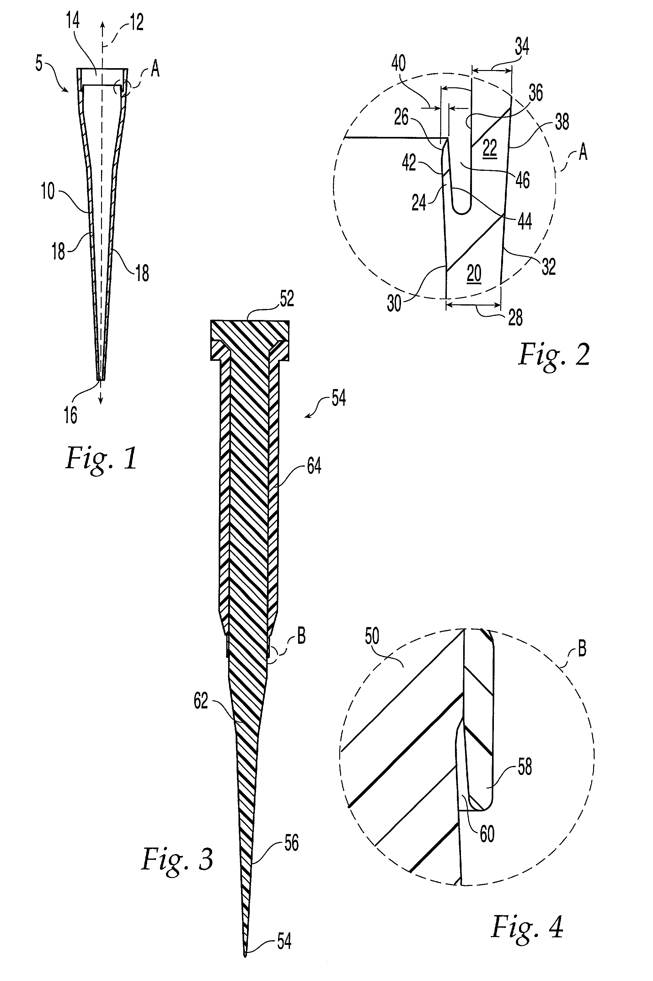
[0014]In FIG. 1, a preferred pipette tip member 5 comprises an elongated tubular receptacle 10 extending along axis 12 having a rear or proximal opening 14 at a proximal end for axially receiving a distal end of a pipette shaft and a tip opening 16 at a distal end for dispensing fluid from the tip member. Receptacle 10 is generally conical in shape having a sidewall 18 that tapers or narrows from the proximal opening 14 to the tip opening 16. Tip member 5 is preferably formed of a plastic material, such as polypropylene.

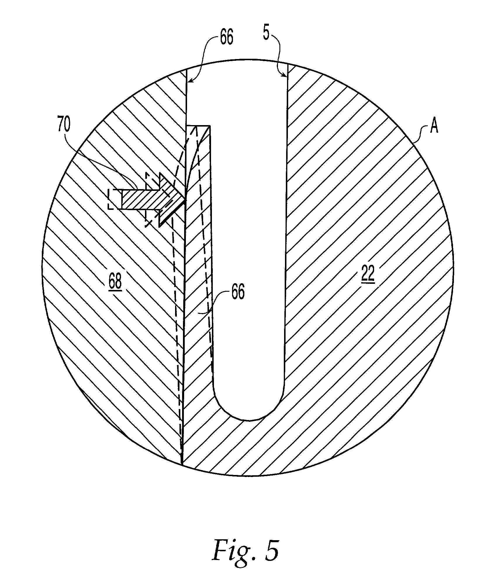
[0015]In a preferred embodiment, sidewall 18 has a bifurcated section, shown in FIG. 1 as section “A”, adjacent the proximal end of receptacle 10. As best seen in the cross-sectional view of FIG. 2, the bifurcated sidewall section comprises a base wall or first sidewall portion 20, with a second sidewall portion 22 and a third sidewall portion 24 that branch from first sidewall portion 20. The second and third sidewall portions 22, 24 extend substantially axially fro...


PUM

PropertyMeasurementUnit
angleaaaaaaaaaa
angleaaaaaaaaaa
lengthaaaaaaaaaa

Abstract

A pipette tip member having an elongated tubular receptacle having a sidewall with a bifurcated section that comprises first, second, and third sidewall portions. The first sidewall portion comprises a base wall and the second and third sidewall portions branch therefrom. The second sidewall portion comprises an outside branch wall, and the third sidewall portion comprises an inside branch wall spaced substantially parallel with and radially inward from the second sidewall portion. The inside branch wall is flexible in the radial direction and engages a pipette tip when it is inserted into the receptacle and to form a fluid-tight seal therewith. A method of forming a pipette tip member is also disclosed.

Description

BACKGROUND OF THE INVENTION[0001]Pipettes and pipette tips come in many configurations. Seals between the pipette and the tip can be formed in several different ways: two conical surfaces coming together, raised rings forming annular pressure points, and a blunt corner or radiused corner forced into a conical tip. To insure a good seal, the pipette must be inserted into the pipette tip with enough force to affect a seal by displacing plastic in the tip. In some instances this force can be considerable.[0002]One solution is proposed in U.S. Pat. No. 4,748,859 to Magnussen, Jr., et al. A disposable pipette tip member is disclosed having three inner coaxial annular sealing bands spaced axially from an open proximal end for receiving a conical pipette tip mounting shaft. The first two sealing bands are relatively resilient and simultaneously engage, guide and laterally support the pipette shaft as it enters the tip member to form annular fluid-tight seals with the shaft. The third band ...

Claims


Application Information

Patent Timeline
Patent Type & Authority Patents(United States)
IPC IPC(8): B01L3/02
CPCB01L3/0279B01L2200/0689B01L2200/087
Inventor BLASZCAK, PETER PAULSPENCER, HOWARD KEITHTAGGART, THOMAS
Owner QUALITY SCI PLASTICS
Why Eureka
Try Eureka