

Filter pipette tip
a filter pipette and tip technology, applied in the field can solve the problems of inability to completely retain the finest droplets and/or particles in the small pores, and achieve the effect of facilitating the differentiation of filter pipette tips
- Summary
- Abstract
- Description
- Claims
- Application Information
AI Technical Summary
Benefits of technology
Problems solved by technology
Method used
Image

Examples
Embodiment Construction
[0068] While this invention may be embodied in many different forms, there are described in detail herein a specific preferred embodiment of the invention. This description is an exemplification of the principles of the invention and is not intended to limit the invention to the particular embodiment illustrated
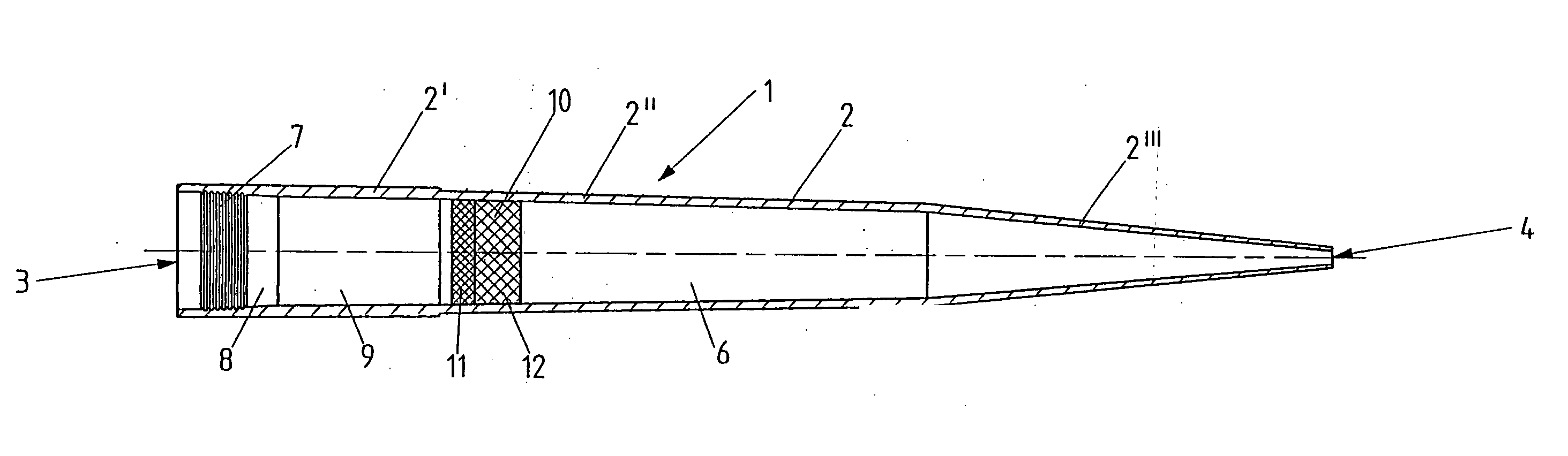
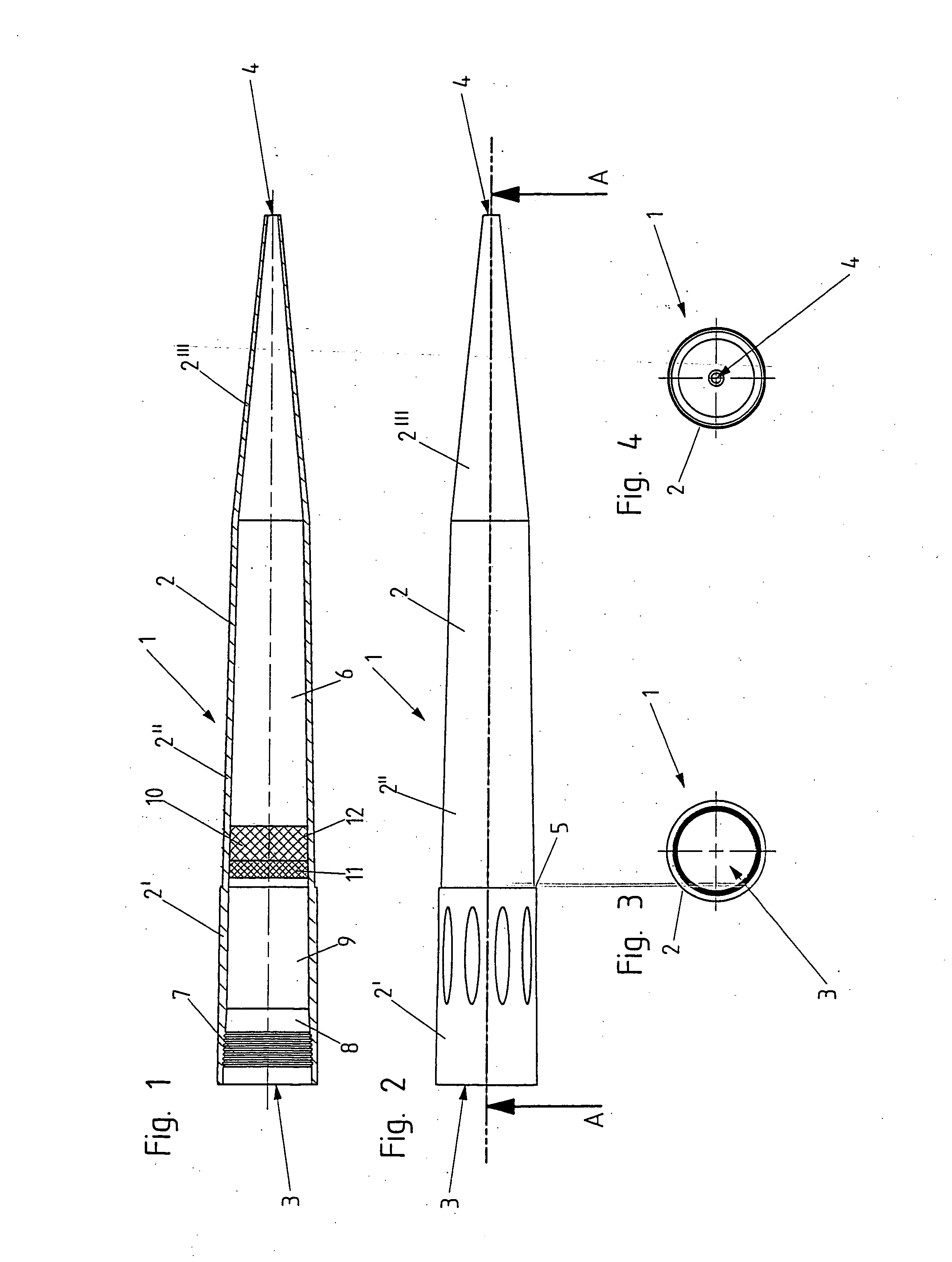
[0069]FIG. 1 is a longitudinal section of the filter pipette tip;
[0070]FIG. 2 is a lateral view of said filter pipette tip;
[0071]FIG. 3 is a top view of said filter pipette tip;
[0072]FIG. 4 is a view from below of said filter pipette tip.
[0073] The filter pipette tip 1 has a small tube 2 which has a relatively large aperture 3 at one end and a relatively small aperture 4 at the other end. Generally, the small tube 2 tapers from the end with the large aperture 3 toward the end with the small aperture 4. Between the apertures 3, 4, said small tube has portions 2′, 2″, 2′″ the portions 2′, 2″ being separated by a shoulder 5. Externally, they have approximately the same conic...
PUM
| Property | Measurement | Unit |
|---|---|---|
| pore sizes | aaaaa | aaaaa |
| pore sizes | aaaaa | aaaaa |
| pore size | aaaaa | aaaaa |
Abstract
Description
Claims
Application Information