Double pass fuel filter assembly

a fuel filter and assembly technology, applied in the direction of moving filter element filters, filtration separation, separation processes, etc., can solve the problems of limited atmospheric pressure, long life of the filter, loss of flow, etc., and achieve the effect of improving filtration

Inactive Publication Date: 2001-06-19
PARKER INTANGIBLES LLC
View PDF63 Cites 91 Cited by
  • Summary
  • Abstract
  • Description
  • Claims
  • Application Information

AI Technical Summary

Benefits of technology

It is an object of the present invention to provide a fuel filter assembly that provides enhanced filtration.
The second media loop removes finer contaminants that have passed through or which have been generated by the lift pump, as fuel passes through the assembly from the second inlet port to the second outlet port. In a first embodiment of the invention, the second media loop is mounted on the replaceable cartridge. The first media loop is fixably mounted to the head portion and is accepted into the cartridge upon engagement of the element portion and the head portion.

Problems solved by technology

This protects the lift pump from contaminants and prolongs its life.
The drawback associated with this position of the fuel filter is that the amount of pressure available to push fuel through the filter is limited to atmospheric pressure.
As a result, severe contamination may block flow and starve other fuel system components causing damage.
Loss of flow may also occur in cold temperatures when wax or ice crystals form in petroleum fuels and block flow through the filter.
A further problem associated with placing the fuel filter on the vacuum side of a lift pump is that lift pumps sometimes fail and generate contaminants.
If these contaminants are carried downstream in the fuel they may cause damage to the high pressure / fuel metering pump or the fuel injectors.
The drawbacks of positioning the fuel filter on the pressure side of the lift pump is that the lift pump is exposed to the contaminants which may shorten its life.
Further, the pumping action tends to entrain the contaminants in the fuel which makes it more difficult to filter them out when they eventually reach the fuel filter assembly.

Method used


Image

  • Double pass fuel filter assembly
  • Double pass fuel filter assembly
  • Double pass fuel filter assembly

Examples


first embodiment

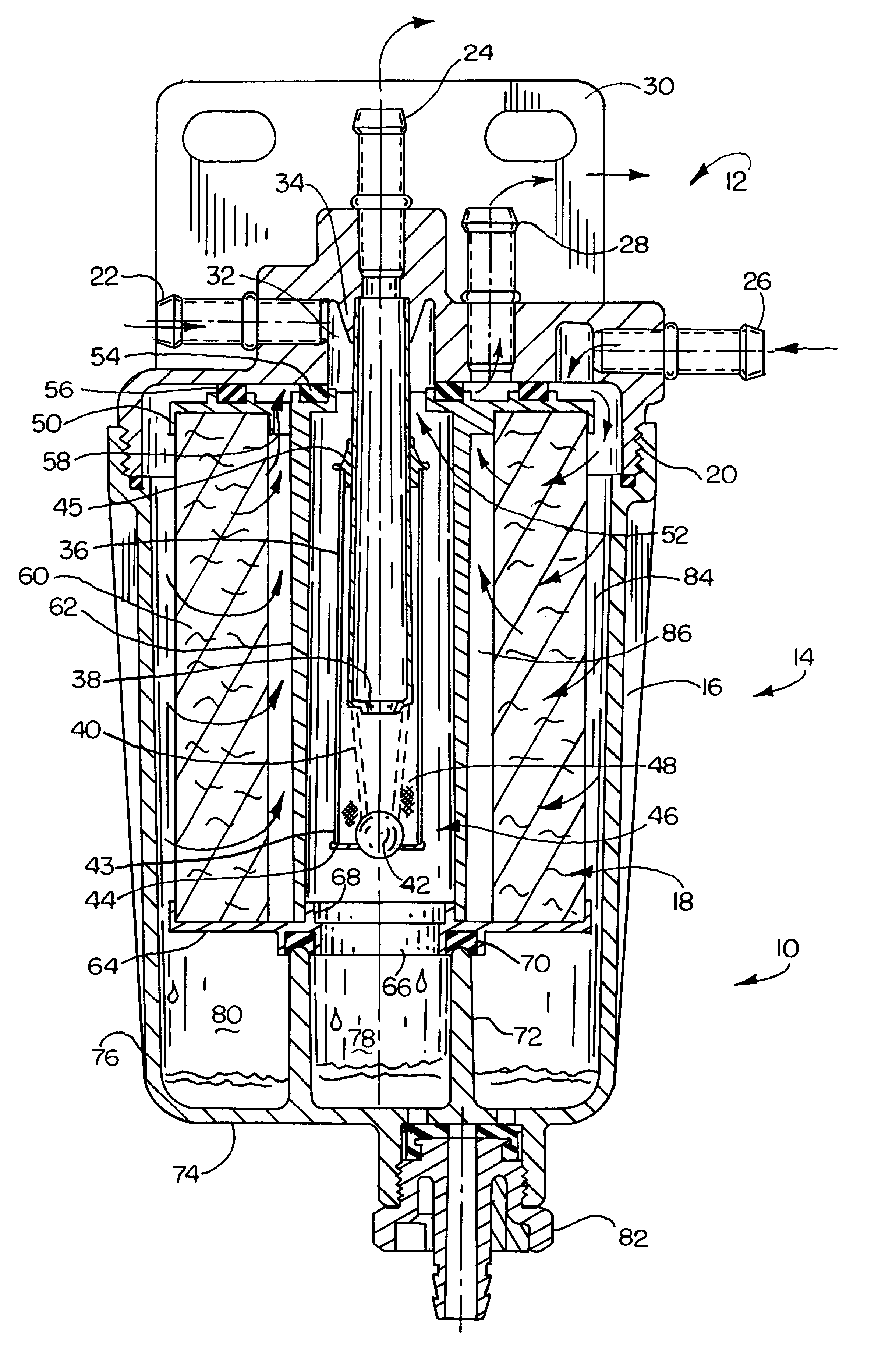
Referring now to the drawings and particularly to FIG. 1, there is shown therein the fuel filter assembly of the present invention generally indicated 10. The fuel filter assembly has a body, which is comprised of a head portion 12 and an element portion 14. The element portion 14 has a housing 16 that encloses a replaceable filter cartridge 18. The housing 16 is selectively attachable to the head portion by inter-engaging threads 20 on the head portion and housing.

The head portion 12 has a first inlet port 22 and a first outlet port 24. The head portion further includes a second inlet port 26 and a second outlet port 28. The head portion 12 also incorporates a bracket portion 30 that facilitates mounting the fuel filter assembly to a vehicle on which it is installed.

Head portion 12 includes a recess 32 which is in fluid communication with inlet port 22. Recess 32 includes a downward extending nipple 34. Nipple 34 is in supporting engagement with a tube 36 which extends downwards in...

second embodiment

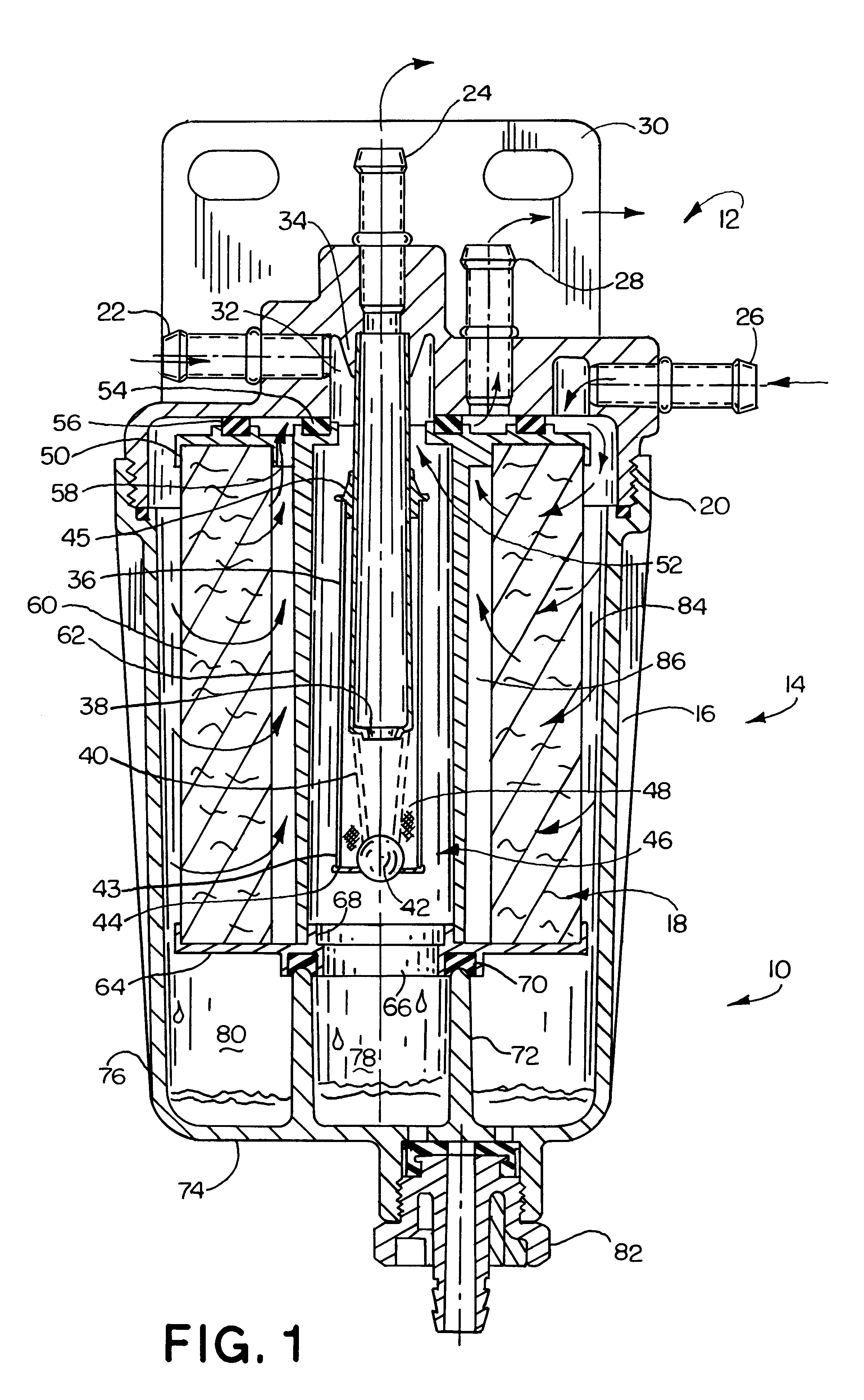
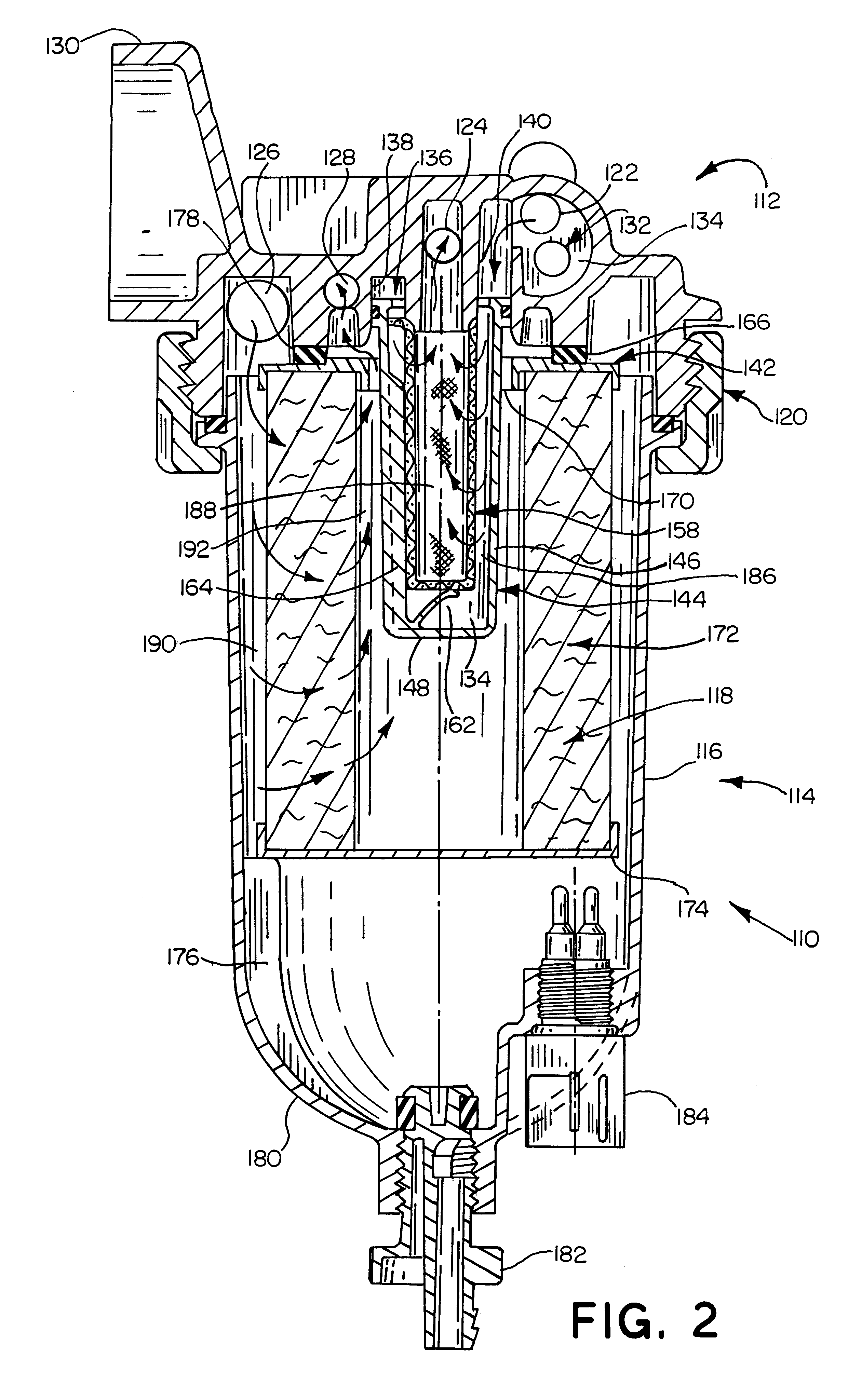
the invention 110 has the advantage that the screen 158 which serves as first media means is replaced each time the cartridge is renewed. As a result, it is assured that the screen is clean after a cartridge change and that restriction to fuel flow is minimized. In addition, the construction of the second embodiment minimizes fuel spillage during element changes. The spent cartridge occupies little volume and reduces the amount of waste that must be discarded, as most of the components of the assembly are reused for the life of the vehicle.

Thus, the new double pass fuel filter assembly of the present invention achieves the above stated objectives, eliminates difficulties encountered in the use of prior devices, solves problems and attains the desirable results described herein.


PUM

PropertyMeasurementUnit
pressureaaaaaaaaaa
atmospheric pressureaaaaaaaaaa
temperaturesaaaaaaaaaa

Abstract

A fuel filter assembly (10) has a head portion (12) and an element portion (14) enclosing a replaceable cartridge (18). The assembly has a first inlet port (22) which accepts fuel from a tank (90) and filters it by passage through a screen (43) supported on a tube (36). The fuel that has been filtered by passage through the screen is delivered from the assembly through a first outlet port (24) for delivery to a lift pump (96). Fuel from the lift pump is returned to the fuel filter assembly through a second inlet port (26). The fuel is finely filtered by passage through a loop of filter media (60). Clean fuel is delivered from a second outlet port (28) to an engine (104). Contaminants separated from the fuel by passage through the screen and the media loop are collected in first-and second sump areas (78), (80) of the filter housing respectively. An alternative embodiment (110) includes a prefilter screen (158) integral with a replaceable cartridge (118).

Description

This invention relates to fluid filters. Specifically this invention relates to a fuel filter assembly for a vehicle that provides enhanced filtration of the fuel prior to delivery to an engine.Vehicle fuel systems typically have a fuel tank for holding a supply of liquid fuel for delivery to an engine. The fuel system also includes a lift pump for pumping fuel from the tank to the engine. Some engines, particularly those that have fuel injection, also have an injection pump which raises fuel pressure beyond that produced by the lift pump so that the fuel may be injected at high pressure into the combustion chambers.Fuel filters are included in fuel systems to remove contaminants such as dirt and water from the fuel before it reaches the engine. Fuel filters are positioned in the fuel system either on the vacuum side or the pressure side of the lift pump. Each position for the fuel filter in relation to the lift pump has advantages and drawbacks.If the fuel filter is positioned on t...

Claims


Application Information

Patent Timeline
Patent Type & Authority Patents(United States)
IPC IPC(8): B01D36/00B01D29/15B01D29/13B01D35/147B01D35/14
CPCB01D29/15B01D35/147B01D36/003B01D36/006B01D29/58B01D35/157B01D35/18B01D35/30B01D2201/302
Inventor HODGKINS, DAVID H.
Owner PARKER INTANGIBLES LLC
Why Eureka
Try Eureka