Fluid feeding system, fluid feeding method and flow channel unit

a technology of fluid feeding system and flow channel, which is applied in the direction of burettes/pipettes, instruments, glassware laboratories, etc., can solve the problems of high water tightness of flow channel, change of flow channel volume, and contamination of flow channel, so as to ensure water tightness between pipettes and flow channel, and prevent decay of flow channel members

Inactive Publication Date: 2006-11-23
FUJIFILM HLDG CORP +1
View PDF0 Cites 75 Cited by
  • Summary
  • Abstract
  • Description
  • Claims
  • Application Information

AI Technical Summary

Benefits of technology

[0012] In view of the foregoing problems, an object of the present invention is to provide a fluid feeding system consisting of a fluid feeding apparatus and a flow channel unit, which achieves sufficient stability in performance and accuracy.
[0022] According to the present invention, either the pipette catchers or the ends of the pipettes are formed from the soft material so as to be deformed resiliently when the ends of the pipettes are pressed onto the pipette catchers, the water-tightness between the pipettes and the flow channel is ensured. Because the ends of the pipettes are just pressed onto the pipette catchers, without being fitted in the inlet and outlet opening, the flow channel is kept at a constant volume, and the removal of the pipettes from the flow channel does not cause waving of the liquid in the flow channel nor accidental separation of the pipettes from the pipette head. Moreover, the present invention prevents decay of the flow channel member and clogging of the flow channel as well, which would be caused by the repetitive insertion and removal of the pipettes.

Problems solved by technology

There is a problem in this configuration that the sample can adhere to the interior of the tube and mix with another sample fluid that flows through the tube afterward.
Such a problem is called contamination.
Thereby, the flow channel gets highly water-tight.
However, the flow channel formed from the elastic material has a problem that the flow channel can be deformed by the inserted pipette tip or the depth of insertion of the pipette tip can vary, which results in changing the volume of the flow channel.
The movement of the pipette into and out of the flow channel vibrates the fluid to wave in the flow channel, and can cause a measurement error if the fluid waves before the measurement.
Moreover, the repetitive insertion and removal of the pipette can decay the flow channel member and cause clogging of the flow channel.
Thus, the insertion of the pipette in the flow channel causes various troubles.
Since the volume variation of the flow channel can cause measurement errors, the above-described assaying method is not sufficiently stable in view of the performance and the accuracy as well.

Method used


Image

  • Fluid feeding system, fluid feeding method and flow channel unit
  • Fluid feeding system, fluid feeding method and flow channel unit
  • Fluid feeding system, fluid feeding method and flow channel unit

Examples


Embodiment Construction

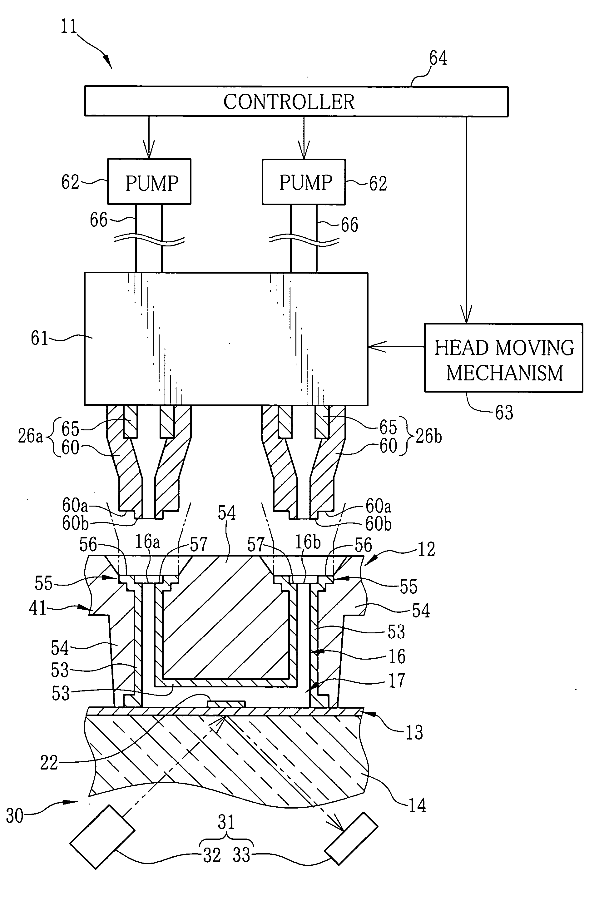
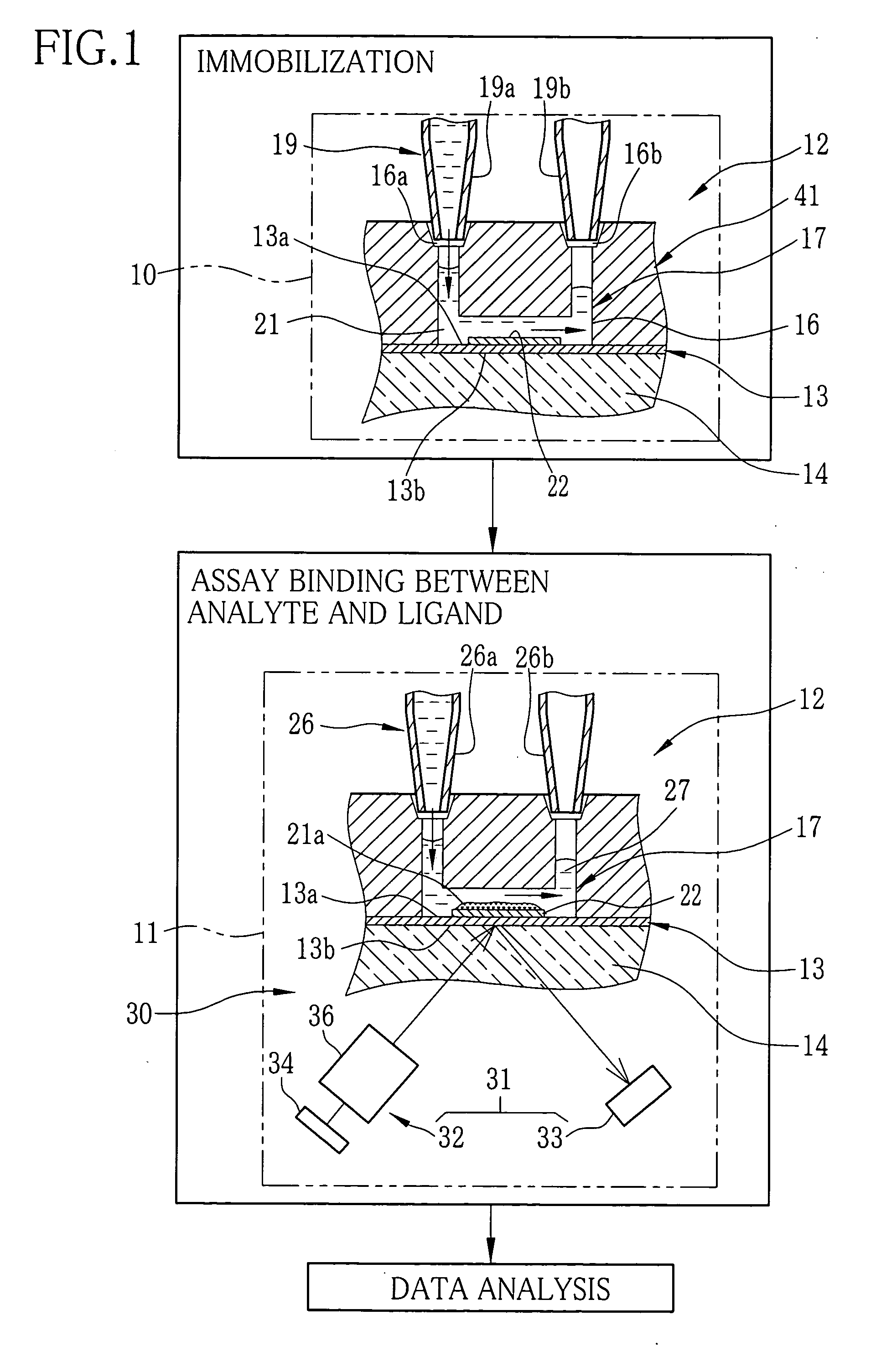
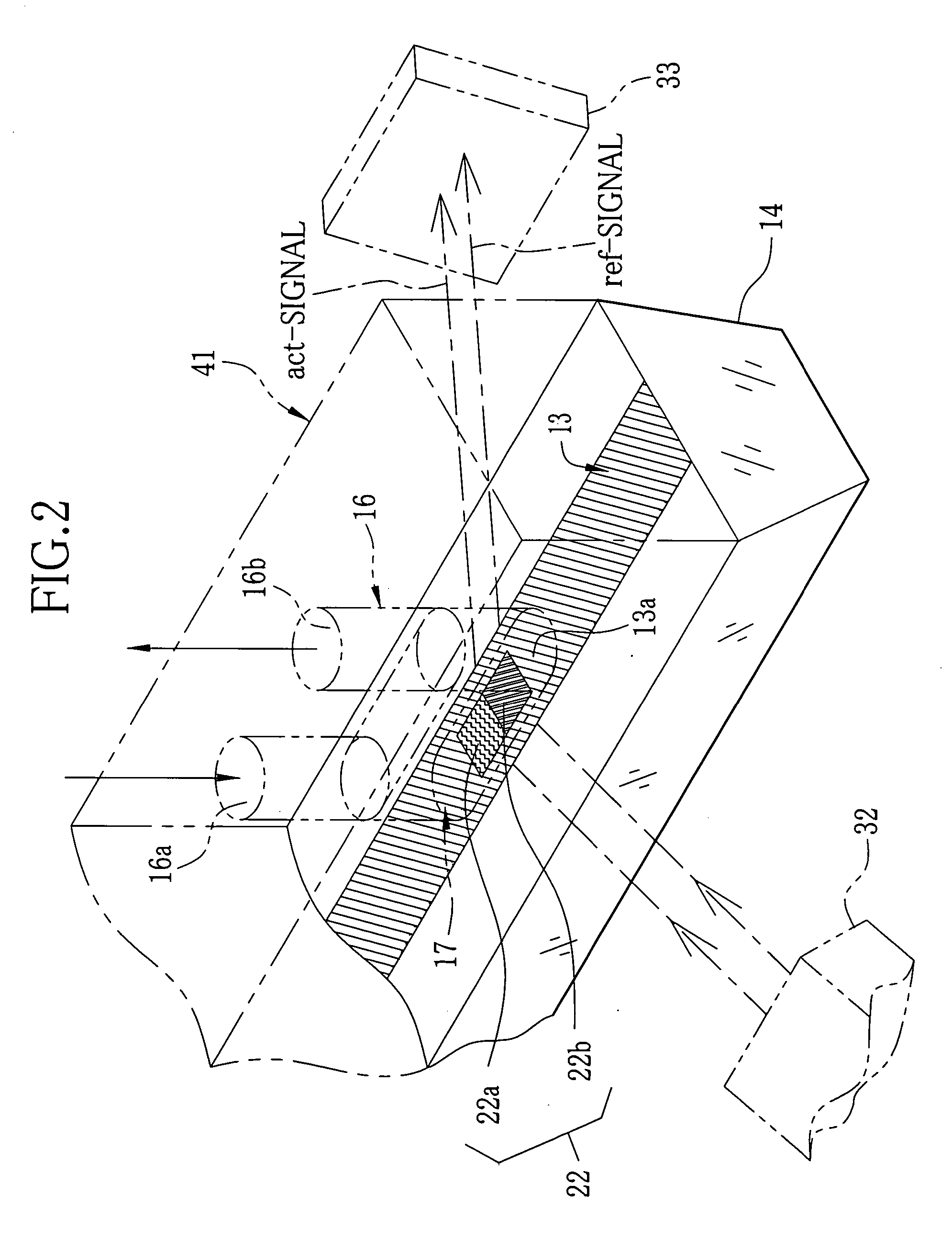
[0034] As shown in FIG. 1, a measuring or assaying method utilizing SPR (surface plasmon resonance) mainly comprises three processes which are an immobilizing process, an assay process and a data analyzing process. An SPR assay apparatus is constituted of an immobilizing device 10 for the immobilizing process, an assay device 11 for the assay process, and a data analyzer for analyzing data obtained through the assay device 11.

[0035] A sensor unit 12 constituting a surface plasmon resonance (SPR) sensor is used for the assay process. The sensor unit 12 includes a metal film 13, a prism 14 and a flow channel member 41. A first surface of the metal film 13 is a sensor surface 13a where the surface plasmon resonance occurs. The prism 14 is joined to a light incident surface 13b that is an opposite surface of the metal film 13 to the sensor surface 13a. The flow channel member 41 is opposed to the sensor surface 13a, and has a flow channel 16 for conducting a fluid such as ligand or ana...


PUM

PropertyMeasurementUnit
thicknessaaaaaaaaaa
diameteraaaaaaaaaa
diameteraaaaaaaaaa

Abstract

A fluid feeding system consists of a flow channel member and a fluid feeding apparatus. The flow channel member has at least a flow channel for feeding a fluid to a sensor surface. Pipette catchers are formed at inlet and outlet openings of the flow channel. The fluid feeding apparatus comprises a movable pipette head having a couple of pipettes, a head moving mechanism and pumps for sucking and ejecting the fluid through the pipettes. To inject the fluid into the flow channel, ends of the pipettes are pressed onto the pipette catchers. The pipette catchers are formed from a soft material, so that they are deformed resiliently when the ends of the pipettes are pressed onto the pipette catchers, thereby ensuring water-tightness between the pipettes and the flow channel, without the need for fitting the pipettes in the inlet and outlet openings.

Description

BACKGROUND OF THE INVENTION [0001] The present invention relates to a fluid feeding system using pipettes for feeding sample fluids into a flow channel, and a fluid feeding method for this system. The present invention relates also to a flow channel unit for use in the fluid feeding system. BACKGROUND OF THE INVENTION [0002] An assay apparatus utilizing attenuated total reflection has been known as a device for assaying reactions of samples, for example, for the purpose of studying interaction of protein, DNA and various biochemical materials, or screening drugs. [0003] A surface plasmon resonance (SPR) sensor is known as such an assay apparatus that utilizes attenuated total reflection. Surface plasmon is a term to mean a compressional wave of free electrons, which moves on the surface of a metal and is caused by mass oscillation of the free electrons inside the metal. [0004] For example, Japanese Patent No. 3294605 discloses an SPR assay apparatus which adopts Kretschmann configur...

Claims


Application Information

Patent Timeline
Patent Type & Authority Applications(United States)
IPC IPC(8): B01L3/02G01N21/11G01N21/27G01N21/41G01N35/02G01N35/08G01N35/10
CPCB01L3/0275B01L3/0293B01L3/502B01L3/565B01L2200/027B01L2200/0642G01N2021/0346B01L2300/0877B01L2300/123B01L2300/14G01N21/05G01N21/11G01N21/553B01L2300/0636
Inventor SHIMIZU, HITOSHI
Owner FUJIFILM HLDG CORP
Why Eureka
Try Eureka