Laser-tethered vehicle

a laser-tethered, vehicle technology, applied in the direction of process and machine control, energy-efficient board measures, instruments, etc., can solve the problems of complex control of such devices, inability to practically hand hold control panels, and involved data communication problems

Inactive Publication Date: 2005-10-18
THE BOEING CO
View PDF15 Cites 82 Cited by
  • Summary
  • Abstract
  • Description
  • Claims
  • Application Information

AI Technical Summary

Benefits of technology

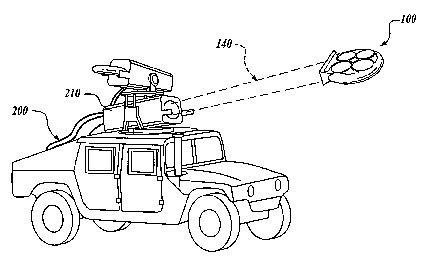
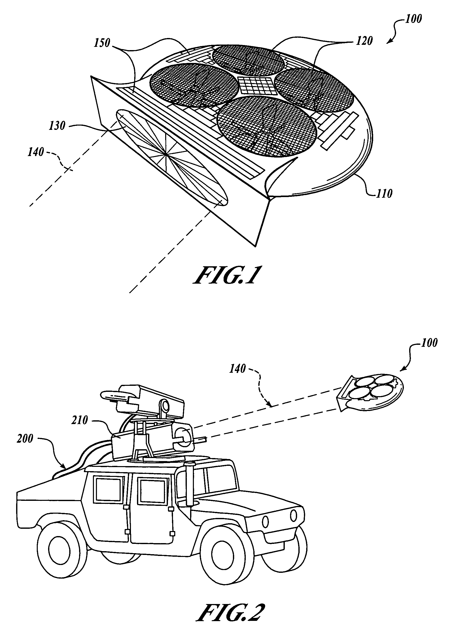
[0010]The present invention provides a system and method for operating a remote-controlled vehicle and a remote-controlled vehicle operated according to the system and method. A preferred embodiment of the present invention includes an unmanned vehicle (UAV) configured to be directable to a point of interest and hover over the point of interest. In contrast with known hovering vehicles that include relatively complex control schemes to maintain the vehicle in a desired position, embodiments of the present invention are guided and powered by an electromagnetic beam generated from a ground source or an aircraft. Using electromagnetic sensors on the vehicle to monitor the position of the electromagnetic beam, the vehicle tracks the position of the electromagnetic beam. Thus, by controlling the position of the electromagnetic beam, the position of the airborne vehicle can be controlled, thereby allowing for surveillance of a desired location or a signal relay point to be positioned at a desired point in space. Other embodiments of the present invention also convert the received electromagnetic energy beam into electrical power for providing at least a portion of the power used in operating the vehicle.

Problems solved by technology

Control of such devices can be a complex problem.
Even high-end hobbyist UAVs have control panels that cannot be practically hand held because of the many levers, dials, switches, and other control devices the operator uses to direct such a device.
Moreover, transmitting the control information from the many control devices, receiving and decoding the instructions at the remote device, and executing the instructions represent involved data communication problems.
In addition, a limitation particularly limiting UAVs is that, like manned aircraft, a UAV has to have the capacity to carry enough fuel or power to complete its mission.
Furthermore, hovering tends to consume substantially more power than forward flight.
However, forward-flight is not an optimal flight mode for all purposes.
For example, forward-flight is not an optimal flight mode for surveillance.
While a forward-flying platform can circle a target of interest, gathering information about the target may be complicated by moving a camera lens or other directional sensor to focus on the target.
Forward-flight also is not optimal for a platform to be used for relaying or redirecting signals.
Hovering vehicles generally consume more power than forward-flying vehicles.
However, in flapping wing flight, aerodynamic flow properties are complex and difficult to manage.
Unfortunately, an efficient way to sustain hovering flight for very long intervals has proven elusive.

Method used


Image

  • Laser-tethered vehicle
  • Laser-tethered vehicle
  • Laser-tethered vehicle

Examples


Embodiment Construction

[0030]By way of overview, embodiments of the present invention provide a method for remote powering and a position control system for a remote-controlled vehicle. An electromagnetic energy receiver is configured to receive an electromagnetic beam. The electromagnetic energy receiver is further configured to determine a position of the remote-controlled vehicle relative to a position of the electromagnetic beam. The vehicle is directed to maneuver to track the position of the electromagnetic beam.

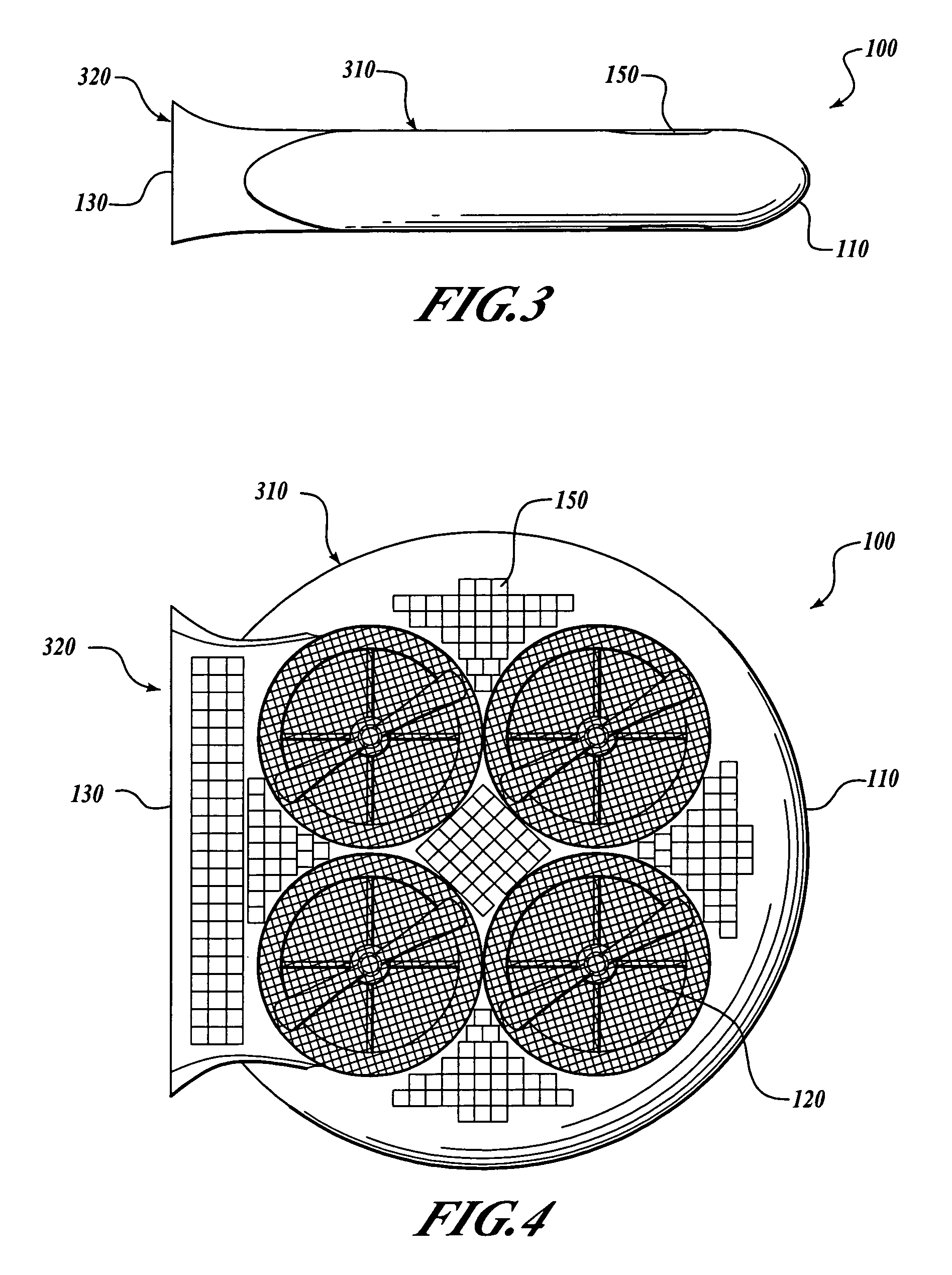
[0031]FIG. 1 is a perspective view of a laser-tethered airborne device 100. The device 100 includes a structure or housing 110 which supports a propulsion system including a plurality of rotors 120. In one presently preferred embodiment, the rotors 120 are disposed to rotate so as to generate thrust in a direction opposed to a gravitational force. One presently preferred embodiment includes a plurality of rotors 120 that are disposed at a distance around a center of gravity of the device 100...


PUM


Abstract

The present invention provides a position control system for a remote-controlled vehicle, a vehicle operated by the control system, and a method for operating a remote-controlled vehicle. An electromagnetic energy receiver is configured to receive an electromagnetic beam. The electromagnetic energy receiver is further configured to determine a position of the remote-controlled vehicle relative to a position of the electromagnetic beam. The vehicle is directed to maneuver to track the position of the electromagnetic beam.

Description

RELATED APPLICATION[0001]This patent application is related to concurrently-filed patent application entitled “VIRTUALLY ATTACHED NODE,”, which is incorporated by reference.FIELD OF THE INVENTION[0002]This invention relates generally to unmanned craft and, more specifically, to remotely controlled vehicles.BACKGROUND OF THE INVENTION[0003]Remote-controlled vehicles, particularly Unmanned Air Vehicles (UAVs), have been in use for years for many different applications. At a simple end, hobbyists steer remote-controlled cars or boats or fly remote-controlled airplanes for entertainment. At a sophisticated end, military and intelligence agencies fly UAVs to conduct surveillance in hostile territories. UAVs are equipped with cameras, microphones, and other sensors to gather intelligence. These sophisticated, complex UAVs are controlled from remote stations.[0004]Control of such devices can be a complex problem. Even high-end hobbyist UAVs have control panels that cannot be practically ha...

Claims


Application Information

Patent Timeline
Patent Type & Authority Patents(United States)
IPC IPC(8): B64C27/20B64C27/00B64C13/00B64C13/20B64C39/00B64C39/02G05D1/00G01S3/786
CPCB64C39/024G01S1/70G01S3/786G05D1/0022G05D1/101B64C2201/208B64C2201/024B64C2201/027B64C2201/042B64C2201/084B64C2201/101B64C2201/108B64C2201/127B64C2201/128B64C2201/146B64C2201/162B64C2201/022B64D2211/00Y02T50/50B64U10/30B64U70/70B64U10/10B64U10/13B64U50/19B64U30/20B64U2101/30B64U2101/60B64U50/14B64U2201/20B64U80/86
Inventor TANIELIAN, MINAS H.
Owner THE BOEING CO
Why Eureka
Try Eureka