Supercharge Your Innovation With Domain-Expert AI Agents!

Inner conductor supports for rigid coaxial transmission lines

a technology of coaxial transmission line and inner conductor, which is applied in the direction of insulated conductors, power cables, cables, etc., can solve the problems of large fabrication load and several significant loads on the insulation support structure of coaxial transmission lines

Inactive Publication Date: 2005-10-18
SPX CORP
View PDF2 Cites 12 Cited by
  • Summary
  • Abstract
  • Description
  • Claims
  • Application Information

AI Technical Summary

Benefits of technology

"The present invention provides an improved coaxial transmission line anchor insulating support that reduces bending and frictional forces, and a method for supporting an inner conductor within an outer conductor of a coaxial transmission line. The invention includes an insulating perimeter ring, an outer portion of which is substantially conformal to the outer conductor, an inner portion of which is substantially displaced from the inner conductor, and a plurality of insulating center conductor facing prongs that are sufficient to contact the inner conductor. The invention also includes various embodiments of the insulating support, such as an insulating perimeter ring with angled prongs, a conically shaped insulating support with trusses of insulating material, and a support with plural insulating center conductor facing prongs. The technical effects of the invention include reducing bending and frictional forces, improving insulation, and providing a more stable and reliable support for the inner conductor."

Problems solved by technology

The insulating support structures in the coaxial transmission line are subject to several significant loads over their life cycle.
Therefore, these fabrication loads can be very large and primarily axially directed rather than radially (though there may be an occasional significant radial component).

Method used


Image

  • Inner conductor supports for rigid coaxial transmission lines
  • Inner conductor supports for rigid coaxial transmission lines
  • Inner conductor supports for rigid coaxial transmission lines

Examples


embodiment 50

[0046]FIG. 5 illustrates another exemplary support embodiment 50 having a hollow cone-like structure. The inner conductor side of the support 50 is terminated with insertion prongs 52 at the “corners” of the support 50. The prongs 52 provide the support 50 the ability to be fixed to the inner conductor 54 via the insertion holes 56 (obstructed from view). The support 50 is illustrated as being generally in the shape of a cone, with the base portion of the cone conformed to the contour of the surface of the inner conductor 54. The support 50 is illustrated as being hollow throughout its entirety, however, various sections of it may be solid, for added reinforcement, as desired. Also, the base of the support 50 may be shaped to allow a greater or lesser plurality of prongs 52 to be formed, than the four (one obstructed from view) shown.

embodiment 60

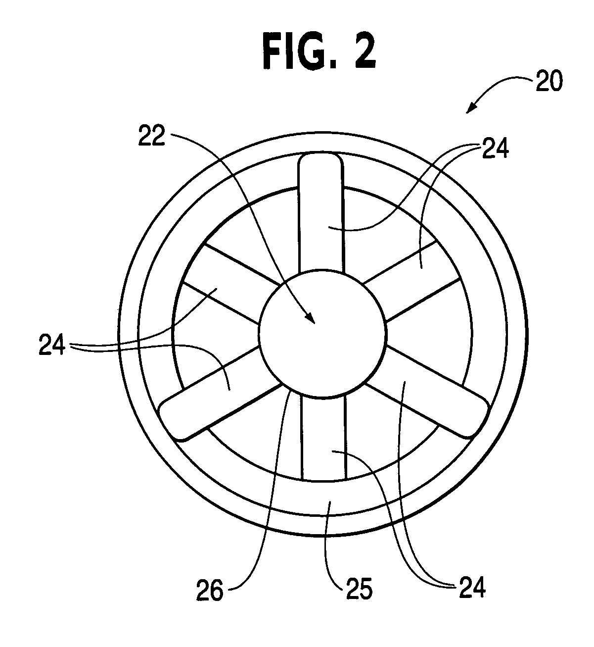
[0047]FIG. 6 illustrates another exemplary support embodiment 60 having a quadro-pod like structure. The support 60 is configured to be similar in many respects to the embodiment of FIG. 5. However, rather than having a conical shape, the exemplary embodiment of FIG. 6 has a semi-tetrahedral or quadro-pod shape. Further, ribs 62 are formed at the “corners” of the support 60 and at the base edge 64. Webbed surface 68 spans the ribs to add additional support. Prongs 66 affix the support 60 to holes in the inner conductor 69.

[0048]FIG. 7 illustrates another embodiment of an exemplary support 70 having a truss-like structure. The base of the base of the support 70 is configured to conform to the surface of the inner conductor 72 and is attached to the inner conductor 72 via prongs 74 and holes (obstructed from view) in the inner conductor 72. Trusses and their various shapes are well known in the art and therefore the available different variations of designs and shapes are not further ...


PUM

PropertyMeasurementUnit
electrical energyaaaaaaaaaa
electrically insulatingaaaaaaaaaa
weightaaaaaaaaaa

Abstract

An support for coaxial transmission lines is described, having a reduced mass and being configured to reduce bending stresses when subject to insertion or axial load effects.

Description

FIELD OF THE INVENTION[0001]The present invention relates generally to transmission line inner conductor support. More particularly, the present invention relates to light weight inner conductor support systems and methods for rigid coaxial transmission lines.BACKGROUND OF THE INVENTION[0002]With the advent of digital television, it has become increasingly important that transmission lines carrying broadcast signals to broadcast antennas convey the signals with minimal attenuation and signal distortion. Conventional transmission lines of the broadcast caliber are usually coaxial in nature and very long, being fabricated from joining several smaller coaxial transmission lines together. To maintain the necessary separation between the inner conductor and outer conductor of the coaxial transmission line, series of insulating supports are interspersed within the line at specified locations. The insulating support structures in the coaxial transmission line are subject to several signifi...

Claims


Application Information

Patent Timeline
Patent Type & Authority Patents(United States)
IPC IPC(8): H01B11/18
CPCH01B11/1856
Inventor BROWN, JEFFREY
Owner SPX CORP
Features
  • R&D
  • Intellectual Property
  • Life Sciences
  • Materials
  • Tech Scout
  • Unparalleled Data Quality
  • Higher Quality Content
  • 60% Fewer Hallucinations
Learn More