Picture placer device

a placer device and picture technology, applied in the field of wallmarking devices, can solve the problems of increasing anxiety, generating angry outbursts, and inconvenient hanging of pictures and other wall hangings, and achieve the effect of effective and efficient hanging of pictures

Inactive Publication Date: 2005-10-25
STROBEL JOHN W
View PDF7 Cites 21 Cited by
  • Summary
  • Abstract
  • Description
  • Claims
  • Application Information

AI Technical Summary

Benefits of technology

[0008]The general purpose of the present invention, which will be described subsequently in greater detail, is to provide a new method and device for effectively and efficiently hanging pictures and the like, while also providing a platform for promotional purposes. The present invention is intended to be used when the picture or art-work to be hung has a picture frame hanging wire secured on both sides of the back of a picture frame. The present invention is not intended for use for picture frames with only a small “saw-tooth” bracket attached to the top of the frame for hanging.
[0009]One objective of the present invention is to provide a device that will accurately mark the wall for the placement of a nail or other hanging hardware.
[0010]Another objective of the present invention is to provide a device that is inexpensive.

Problems solved by technology

Hanging a picture and other wall hangings has traditionally been an imprecise, awkward and frustrating procedure for most people, particularly when the elements supporting the picture are concealed by the picture itself.
When multiple people are involved or multiple pictures are to be hung in precise alignment to each other, the anxiety level increases, sometimes to the level of generating angry outbursts.
This repositioning generally results in multiple disfiguring marks or holes on the wall, either from the pencil, the nail, or both.
While these patents and other previous methods have attempted to solve the problem of marking the wall to facilitate the proper hanging of pictures and the like, none have employed an imprintable front flange, disposed for promotional purposes, a flexible shape-changeable finger-grip loop and a centering window.
Additionally, prior inventions such as that disclosed by the Deaton patent, are not lockable and have limited adjustability.

Method used


Image

  • Picture placer device
  • Picture placer device
  • Picture placer device

Examples


Embodiment Construction

[0048]Before explaining the disclosed embodiment of the present invention in detail it is to be understood that the invention is not limited in its application to the details of the particular arrangement shown since the invention is capable of other embodiments. Also, the terminology used herein is for the purpose of description and not of limitation.

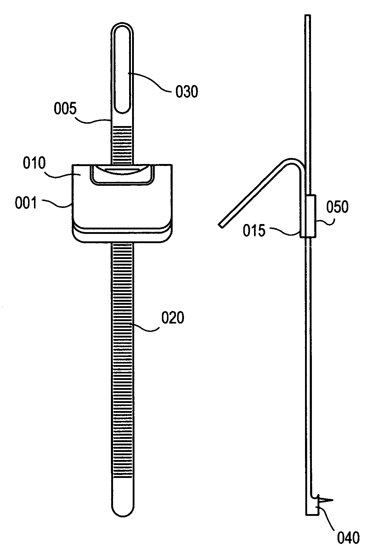
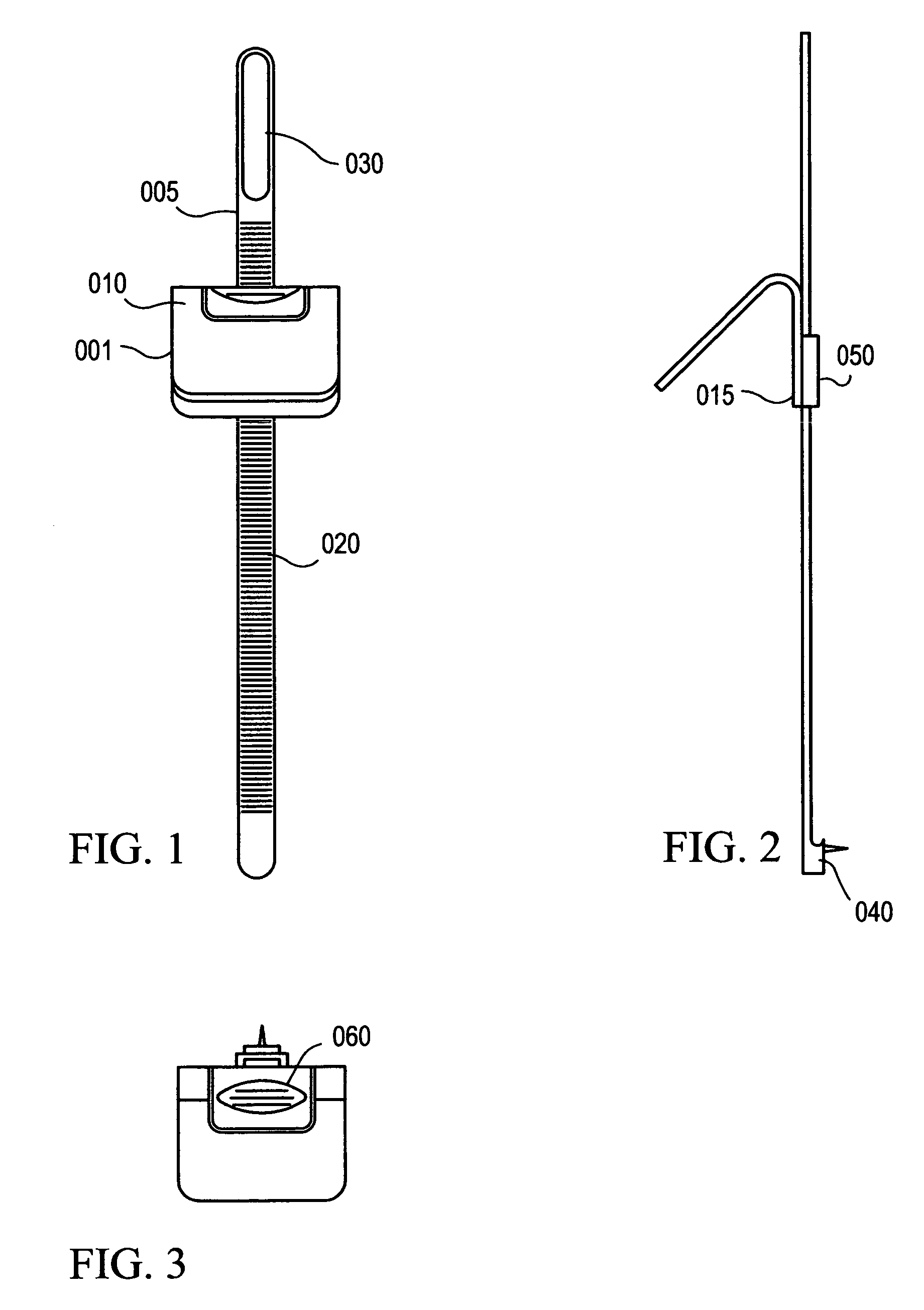
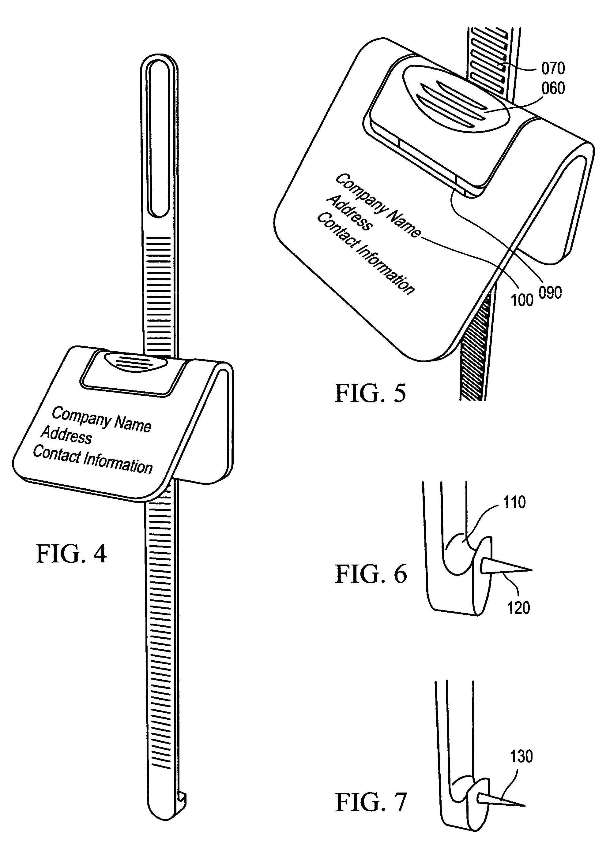
[0049]The preferred embodiment of the present invention is comprised of the following. The wire retrieval arm, 005, is further comprised of a finger grip loop, 030, retrieval arm teeth, 020, disposed on the front side of the wire retrieval arm, 005, a hook and marking assembly, 040, at the bottom of the wire retrieval arm, 005, with the hook and marking assembly, 040, disposed on the back side of the wire retrieval arm, 005, opposite of the retrieval arm teeth, 020. The hook and marking assembly, 040, is further comprised of a wire retrieval arm hook, 110, and a wall marking appendage, 120. The present invention is further comprised of...


PUM


Abstract

A device and method for locating the point on a wall at which a nail, or other wire suspending element, is to be installed for the hanging of pictures and the like. The device includes a retrieval arm operable for engaging the framing wire of a picture and a wall striking element operable for marking on a wall the place for a nail or other hardware to be secured. The device also includes a flanged assembly operable for receiving the retrieval arm and selectively engaging and disengaging the retrieval arm. The flanged assembly is disposed for promotional information or attachments.

Description

BACKGROUND OF THE INVENTION[0001]The present invention relates to wall-marking devices which facilitate the installation of pictures, artwork, mirrors, and other wall-mounted articles, particularly where such articles are supported from behind by a catch such as a wire or cord. Also, the present invention relates to a method of marking the wall at the proper site for the hanging device, in order that the frame of the hanging device will hang in the precise position desired, while being centered and level, all while allowing both hands to be free to hold the artwork. Additionally, the present invention relates to the provision of the display of promotional information, whether in the form of text, color, shapes, logos and the like.[0002]Hanging a picture and other wall hangings has traditionally been an imprecise, awkward and frustrating procedure for most people, particularly when the elements supporting the picture are concealed by the picture itself. When multiple people are invol...

Claims


Application Information

Patent Timeline
Patent Type & Authority Patents(United States)
IPC IPC(8): A47G1/24A47G1/16B60R1/02A47G1/20G09F7/18
CPCA47G1/205G09F7/18
Inventor STROBEL, JOHN W.
Owner STROBEL JOHN W
Why Eureka
Try Eureka