
Connector and receptacle containing a physical security feature

a technology of physical security and connectors, applied in the direction of coupling device connections, instruments, optical elements, etc., can solve the problems of increasing the popularity of fttd applications, affecting the reliability of fttd connectors, and challenging the connection of independent fiber optic cables

Inactive Publication Date: 2005-11-01
COMMSCOPE TECH LLC
View PDF27 Cites 70 Cited by
  • Summary
  • Abstract
  • Description
  • Claims
  • Application Information

AI Technical Summary

Problems solved by technology

Connecting independent fiber optic cables can be challenging due the nature of optical fiber.
The growth of FTTD applications complicates the requirements of optical connectors.
The increased popularity of FTTD applications creates a new problem as many large networks implement SFF connectors such as the MT-RJ connector.
While some access limitation can be obtained through the use of software (e.g., passwords), further limitations are desirable using some type of physical barrier to the networks.

Method used


Image

  • Connector and receptacle containing a physical security feature
  • Connector and receptacle containing a physical security feature
  • Connector and receptacle containing a physical security feature

Examples


Embodiment Construction

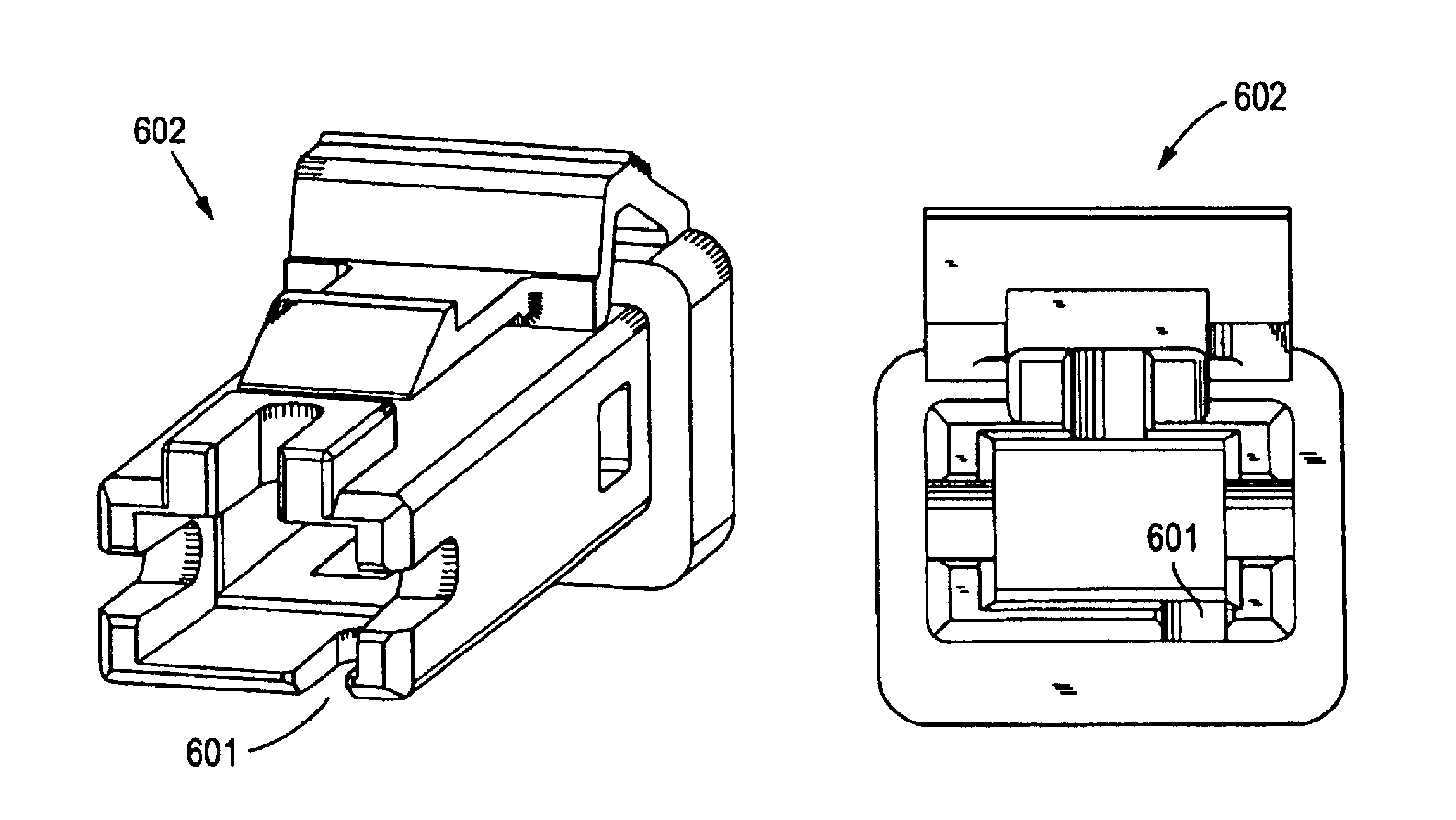
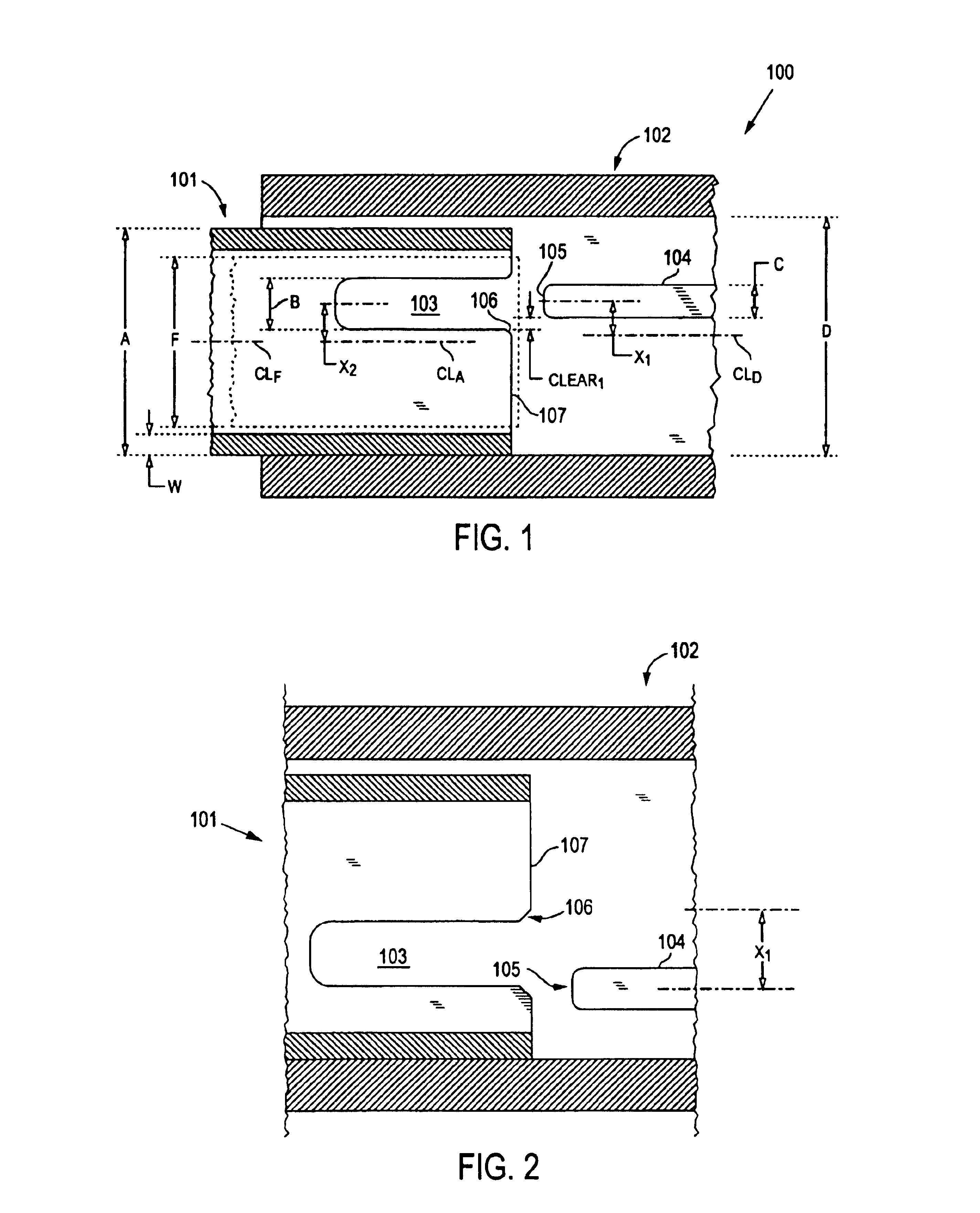
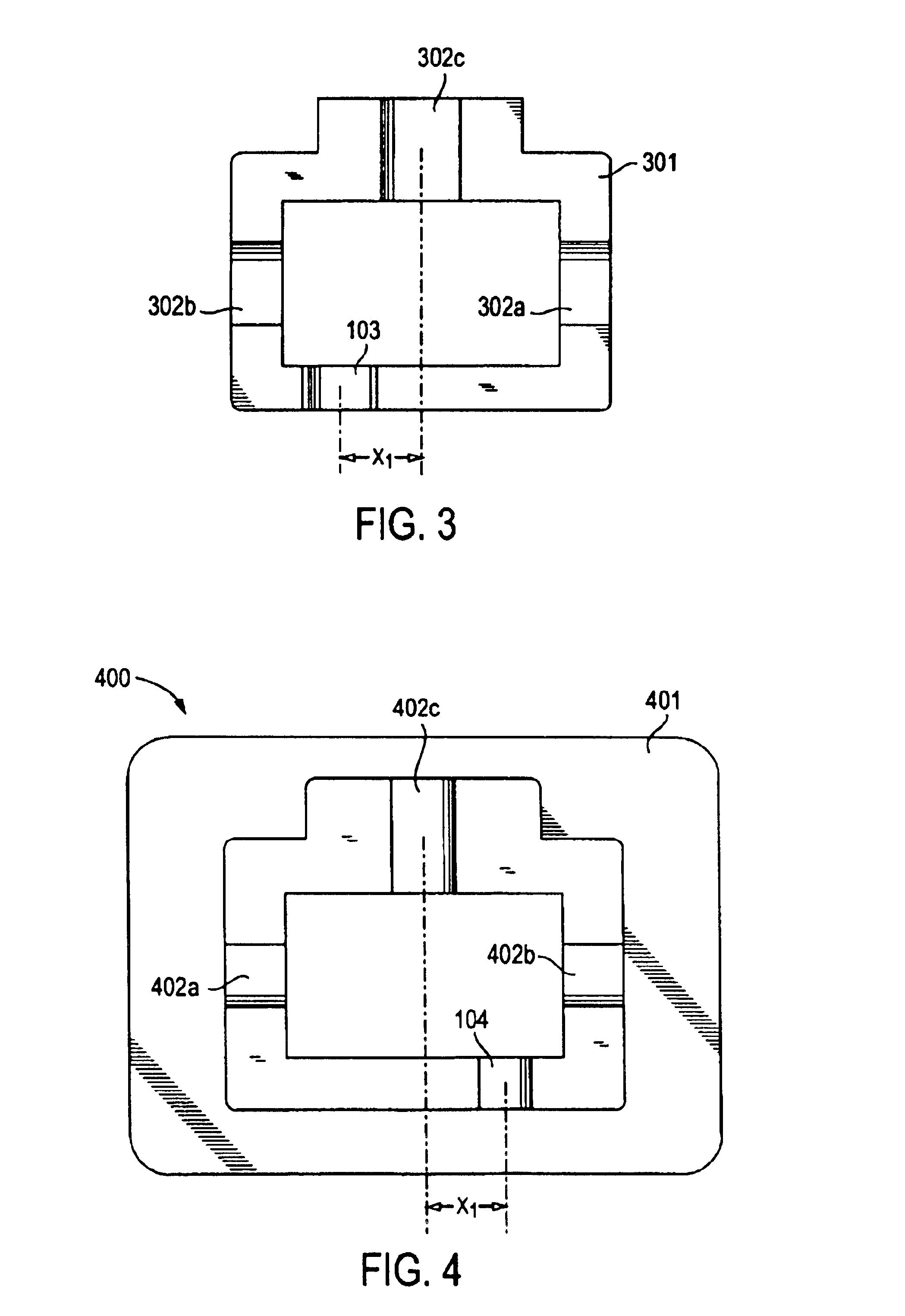
[0019]The present invention relates to a connector system comprising a series of connector components which interconnect with each other in a discretionary way. Referring to FIG. 1, a preferred embodiment of a mating plug 101 and receptacle 100 of the connector system is illustrated. As shown, the plug 101 is partially inserted into the receptacle 100, which, in this embodiment, is a jack having a tub portion 102. Although a jack is discussed herein in detail, it should be understood that the receptacle of the present invention is not restricted to a jack and may be any structure configured to receive a plug, including, for example, an adapter for connecting two plugs together or an integral connector on an active device (e.g., transceiver) or passive device (e.g., splitter).

[0020]The plug typically contains a conductive element such a fiber or wire which mates with a similar element in the receptacle. In fiber optic applications, it is common for the conductive element to be contai...


PUM


Abstract

A connector system that provides discriminating mating between plugs and receptacles by using a system of geometrically matched connector components which allow certain pairs of connectors to mate but which prevent all other combinations of connectors to mate.In a preferred embodiment, the connector system comprises (a) a plurality of receptacles, each receptacle having an inner surface with a first geometry; (b) a plurality of plugs, each plug having a second geometry; (c) wherein the second geometry of a plug cooperates with at least one first geometry of a receptacle to allow the plug and the at least one receptacle to mate, while the second geometry of the plug physically interfering with all other second geometries of all of the other receptacles of the plurality of receptacles to prevent mating therewith.

Description

CROSS REFERENCE TO RELATED APPLICATIONS[0001]This application claims priority to U.S. Provisional Application No. 60 / 218,705, filed Jul. 17, 2000.FIELD OF THE INVENTION[0002]The present invention relates to connectors for the use with fiber optics, and more specifically relates to a system of novel key-slot structures to provide several mutually exclusive connectors for discriminating between users.BACKGROUND OF THE INVENTION[0003]Fiber optic communication systems have become increasing more popular in recent years. Fiber optic technology provides several advantages over the conventional copper wire-based technology. For example, fiber optic communication systems provide substantially increased bandwidth and allow for large volumes of data to be transferred quickly over long distances. In addition, these communications systems are not susceptible to electromagnetic interference (EMI).[0004]With the increase in use of fiber optic systems, connectors have become necessary for connecti...

Claims


Application Information

Patent Timeline
Patent Type & Authority Patents(United States)
IPC IPC(8): G02B6/38
CPCG02B6/3831G02B6/3873G02B6/3881G02B6/3893
Inventor GURRERI, MICHAEL
Owner COMMSCOPE TECH LLC
Learn More