
Non-contact electromagnetic illuminated detection of part anomalies for cyber physical security

a technology of cyber physical security and illuminated detection, applied in the direction of unauthorized memory use protection, instruments, wireless communication, etc., can solve the problems of inability to influence pre-existing devices to a wide range of degrees, existing methods or solutions typically do not address the detection of changes already or previously placed in firmware or hardware circuitry, and existing methods may require intrusive means

Active Publication Date: 2015-12-10
NOKOMIS
View PDF8 Cites 33 Cited by
  • Summary
  • Abstract
  • Description
  • Claims
  • Application Information

AI Technical Summary

Benefits of technology

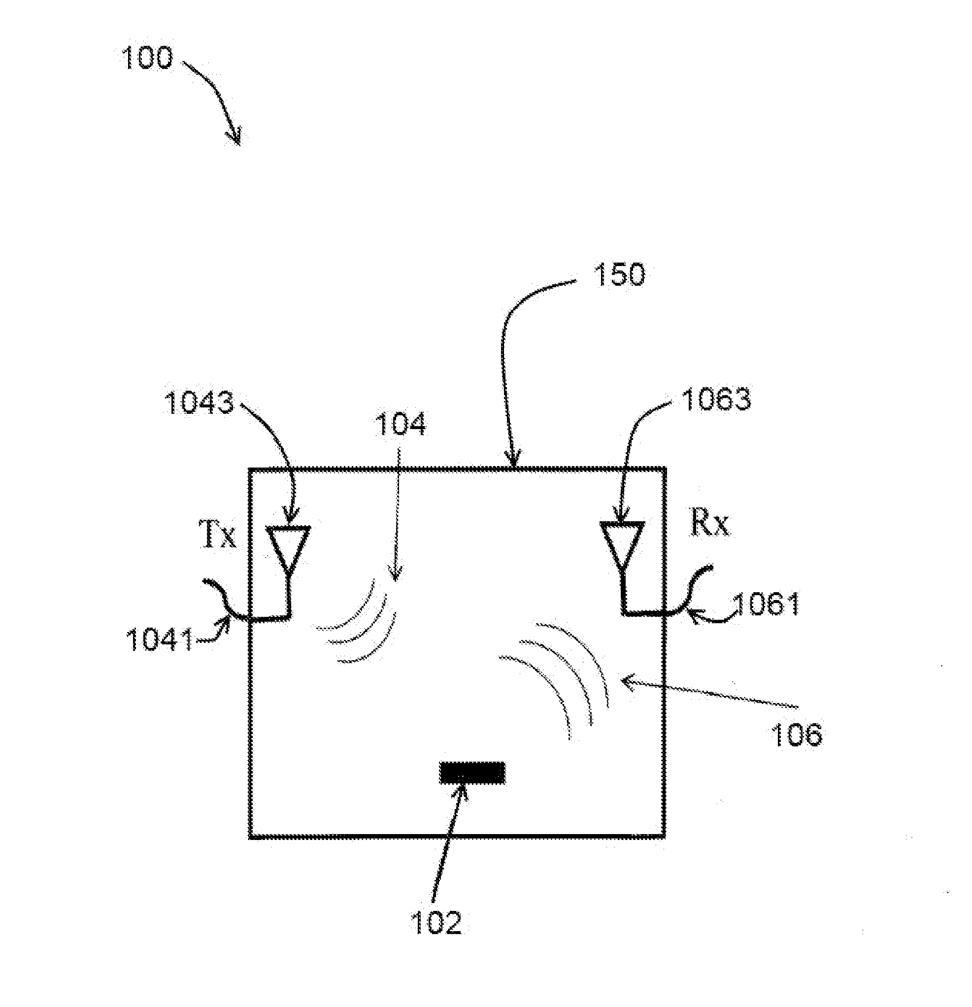
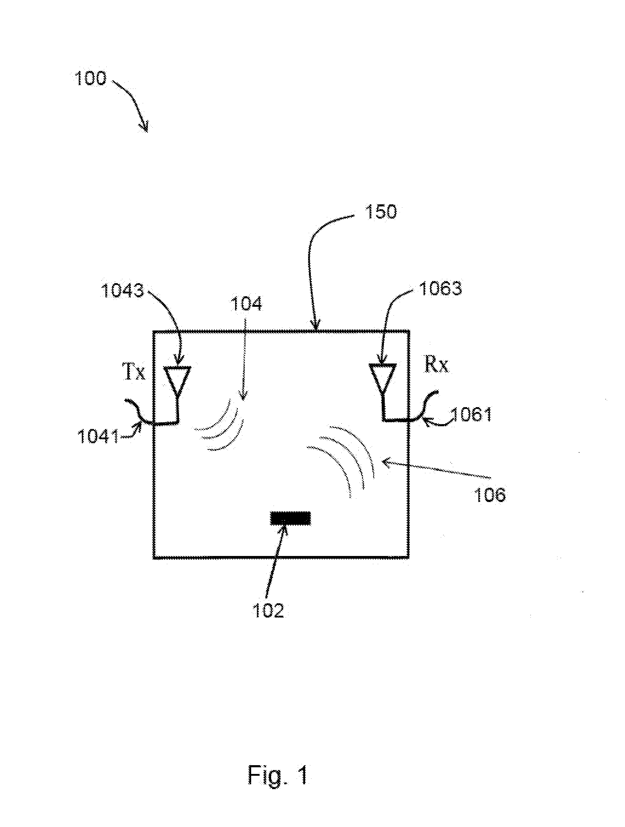
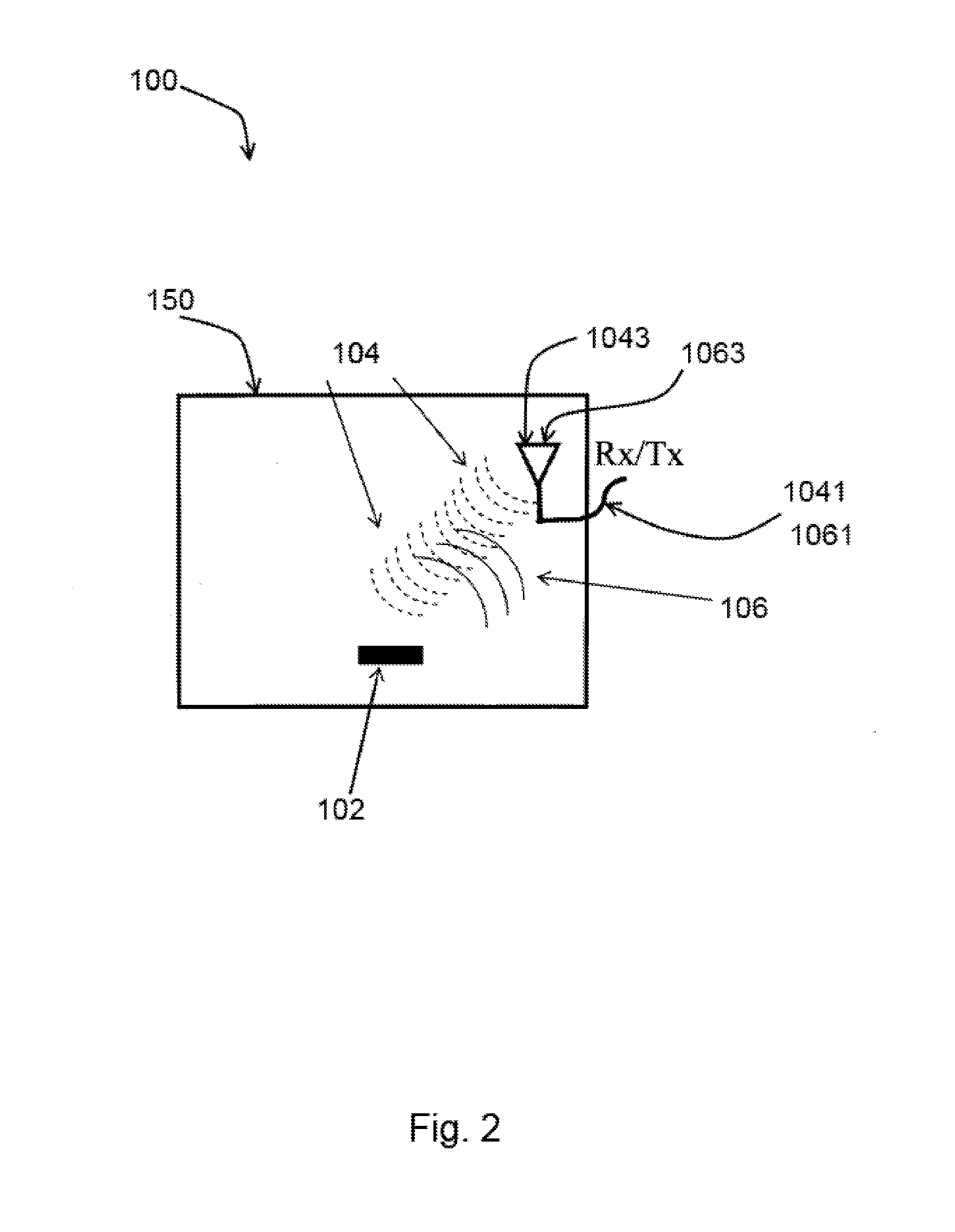
The patent describes an invention that uses RF illumination to detect detailed information about electrical devices. It can detect changes or modifications in hardware, software, or firmware, by analyzing the unintentional electromagnetic emissions that the device emits during RF illumination. The invention can perform this detection without needing to attach any additional fixtures to the device. It can also detect physical, firmware, or software-based anomalies in the device. The RF illumination is directly coupled to the device's body or circuit board traces, allowing for a more direct and accurate analysis. Overall, the technology provides a way to non-invasively inspect electrical devices and improve their reliability and security.

Problems solved by technology

Further, conventional solutions may not be capable of influencing pre-existing devices to a wide range of degrees, especially while the devices are under operation ranging from undetectable to the device under test, to inducing specific selected changes in RF emissions and associated operational influences on pre-existing specific hardware components based on design choices and features, subsystems or components contained therein, to complete disablement of the operating device, to permanent disablement of the device.
The existing methods or solutions typically do not address the detection of changes already or previously placed in firmware or hardware circuitry.
Further, the existing methods may require an intrusive means, typically including added hardware or software components to the system, effectively modifying its design and / or modifying system's operation to accomplish intended goal(s).
The existing methods typically may not be performed in a non-contact, undisturbed, non-powered, unmoved manner and / or an undetectable manner and / or at a distance from a questionable device.
For example, the conventional solutions typically may not detect deliberately concealed and temporarily inactive malicious hardware or firmware modifications lurking in an infected system and waiting to be automatically invoked or unleashed when triggered by a condition, a signal combination, a status change or any combinations thereof.
The conventional solutions may not be implemented in a separate, portable, unobtrusive, non-contact, and attachment-not-needed devices for inspection of suspected equipment.
The conventional solutions may not function without modification of or addition to the aggregate digital signaling to or within, digital processing, or logical operations of the device under test, inspection and / or screening.
The conventional solutions typically may not improve accuracy by acquiring a baseline of operations, baseline characteristics, or baseline behavior, without a period of intrusive changes such as data acquisition periods while operating nominally and executing on a known-good system and cannot do this at a distance.
The conventional solutions typically may not geolocate or locate an electronic device or area within such device associated with a source of emissions indicating the presence of such undesired modifications or lack of modifications in hardware or firmware.
The conventional solutions may not invoke state changes which selectively activate, modify or inhibit such malware activity or malware in firmware activity results from a distance by active Radio Frequency (RF) illumination.
The conventional solutions may not determine if active RF illumination has succeeded in a desired malware mitigation state change from an illumination source disposed remotely, at distance, from the device under testing inspection and / or screening.

Method used


Image

  • Non-contact electromagnetic illuminated detection of part anomalies for cyber physical security
  • Non-contact electromagnetic illuminated detection of part anomalies for cyber physical security
  • Non-contact electromagnetic illuminated detection of part anomalies for cyber physical security

Examples


Embodiment Construction

[0045]Prior to proceeding to the more detailed description of the claimed subject matter it should be noted that, for the sake of clarity and understanding, identical components which have identical functions have been identified with identical reference numerals throughout the several views illustrated in the drawing figures.

[0046]The following detailed description is merely exemplary in nature and is not intended to limit the described examples or the application and uses of the described examples. As used herein, the words “example”, “exemplary” or “illustrative” means “serving as an example, instance, or illustration.” Any implementation described herein as “example”, “exemplary” or “illustrative” is not necessarily to be construed as preferred or advantageous over other implementations. All of the implementations described below are exemplary implementations provided to enable persons skilled in the art to make or use the embodiments of the disclosure and are not intended to li...


PUM


Abstract

An apparatus for testing, inspecting or screening an electronic device for electrical characteristics, modified or unmodified hardware, or firmware modifications including Malware, Trojans, improper versioning, and the like, includes a transmitting antenna positioned at a distance from the electronic device and a electromagnetic energy receiver or sensor for examining a resulting unintentional derived electromagnetic energy from the electronic device. The receiver collects unintentional RF energy components emitted by the device and includes a processor and executable instructions that perform analysis in a response to the acquired electromagnetic energy input. The characteristics of the collected RF energy may be compared with RF energy characteristics of an exemplary device. The analysis determines one of a modified, unmodified or score of certainty of discerned condition of the device.

Description

CROSS REFERENCE TO RELATED APPLICATIONS[0001]This patent application is related to and claims priority from U.S. Provisional Patent Application Ser. No. 61 / 997,745 filed Jun. 9, 2014 and its disclosure is being incorporated into this document by reference thereto.[0002]This document incorporates by reference the disclosures and / or teachings of the following documents: U.S. Pat. No. 7,515,094 (“Advanced electromagnetic location of electronic equipment”); U.S. Pat. No. 8,063,813 entitled “Active improvised explosive device (IED) electronic signature detection”; U.S. Pat. No. 8,537,050 entitled “Identification and analysis of source emissions through harmonic phase comparison”; U.S. Pat. No. 8,643,539 entitled “Advance manufacturing monitoring and diagnostic tool”; U.S. Pat. No. 8,825,823 entitled “System and method for physically detecting, identifying, diagnosing and geolocating electronic devices connectable to a network”; US Pub 20100123453 entitled “ADVANCE MANUFACTURING MONITORIN...

Claims


Application Information

Patent Timeline
Patent Type & Authority Applications(United States)
IPC IPC(8): H04L29/06
CPCH04L63/1416G06F21/56G06F21/577G06F21/73G06F2221/034H04L63/0876H04W12/128H04W12/65G06F11/00
Inventor KELLER, WALTER JOHN
Owner NOKOMIS
Learn More