Al technical title is built by PatSnap Al team. It summarizes the technical point description of the patent document.
a technology for physical security and computers, applied in clothing locks, building locks, construction, etc., can solve the problems of reducing the theft potential of the mechanism, difficult to resell, and difficult to apply sufficient leverage to break the mechanism away from the equipment to which it is attached
Inactive Publication Date: 2006-09-26
ACCO BRANDS USA LLC
View PDF307 Cites 33 Cited by
Summary
Abstract
Description
Claims
Application Information
AI Technical Summary
This helps you quickly interpret patents by identifying the three key elements:
Problems solved by technology
Method used
Benefits of technology
[0011]The present invention provides apparatus which inhibits the theft of equipment such as personal computers. The equipment must have an external wall provided with a specially designed, approximately rectangular slot having preselected dimensions. An attachment mechanism includes a housing for a spindle having a first portion rotatable within the housing, a shaft extending outwardly from the housing, and a crossmember at the end of the shaft having peripheral dimensions closely conforming to the internal dimensions of the slot. An abutment mechanism also emanates from the housing, and is located on opposite sides of the shaft intermediate the housing and the crossmember. The peripheral cross-sectional dimensions of the abutment mechanism and the shaft in combination closely conform to the dimensions of the slot. The length of the shaft from the housing to the crossmember is approximately equal to the thickness of the external wall of equipment. The crossmember is aligned with the abutment mechanism so that the crossmember can be inserted through the slot with the shaft and the abutment mechanism occupying the slot. The spindle is then rotated 90° to misalign the crossmember with the slot, thereby attaching the attachment mechanism rigidly to the external wall. A cable is secured to the housing and to an immovable object so that the equipment cannot be stolen.
Problems solved by technology
In the preferred embodiments, the mechanism is quite small, and it is difficult to apply sufficient leverage to break the mechanism away from the equipment to which it is attached.
Forcibly removing the mechanism will result in significant, highly visible damage to the exterior wall, identifying the equipment as stolen and making it difficult to resell, greatly reducing its theft potential.
Method used
Image
Click on the blue label to locate the original text in one second.
Reading with bidirectional positioning of images and text.
Examples
Embodiment Construction
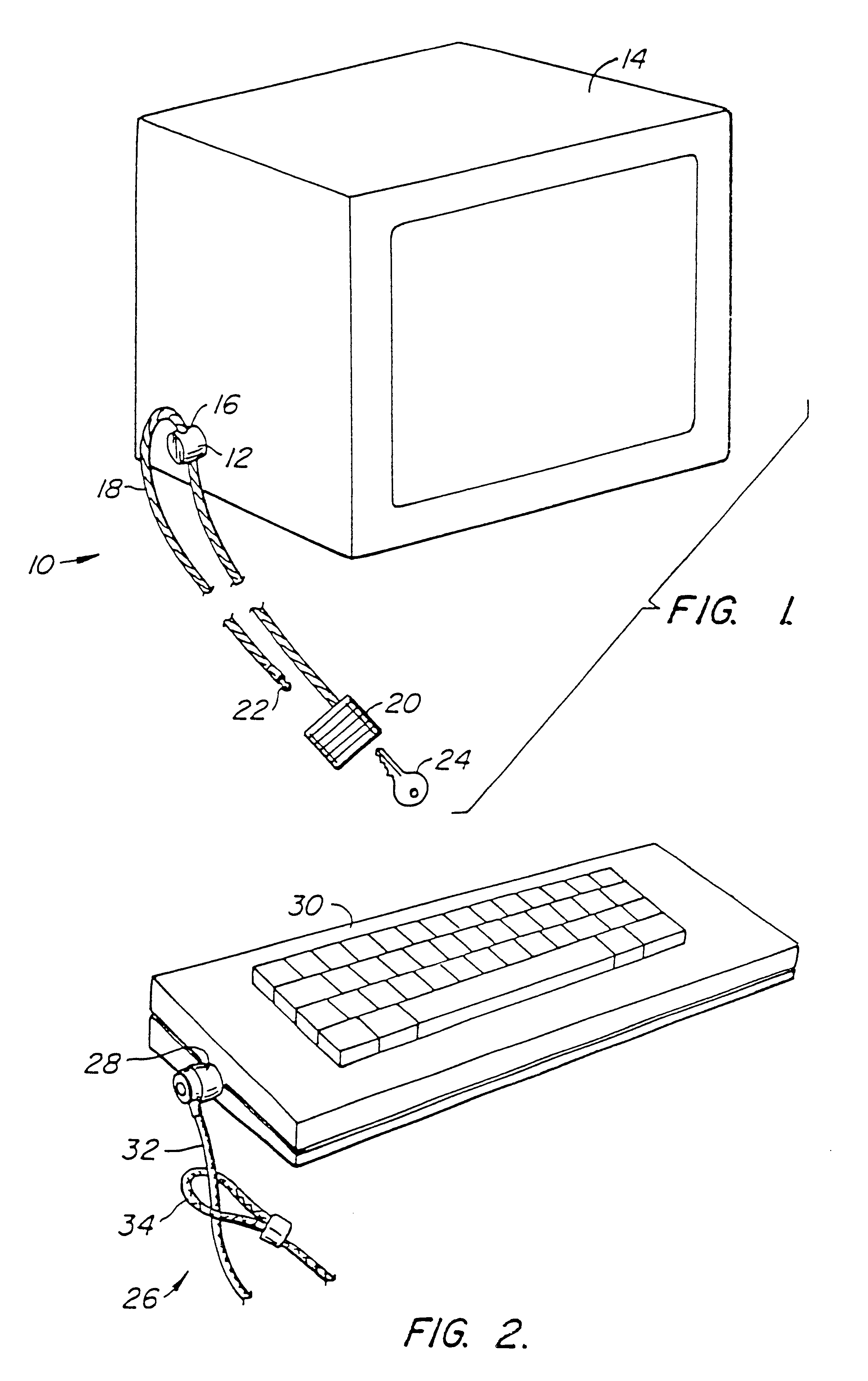
[0050]A first preferred embodiment 10 of the security device of the present invention is illustrated generally by way of reference to FIG. 1. Security device 10 includes an attachment mechanism 12 designed to attach to a component of a computer system, such as computer monitor 14. Attachment mechanism 12 has an aperture 16, and a cable 18 which passes through the aperture when the attachment mechanism 12 is attached to a component such as monitor 14. A lock 20 is fixed to one end of cable 18. The free end of cable 18 may be of the type having a “mushroom” head 22 adapted to penetrate and be secured within lock 20 using key 24. With mushroom head 22 detached from lock 20, cable 18 can be threaded through the apertures 16 of one or more attachment mechanisms 12, and wrapped around a relatively immovable object (not shown) such as the cross bar spanning two legs of a desk. Mushroom head 22 is then inserted into lock 20 and the lock closed using key 24 to secure the computer components ...
PUM
Abstract
An apparatus which inhibits the theft of equipment such as personal computers is disclosed. The equipment must have an external wall provided with a specially designed, approximately rectangular slot having preselected dimensions. An attachment mechanism includes a housing for a spindle having a first portion rotatable within the housing, a shaft extending outwardly from the housing, and a crossmember at the end of the shaft having peripheral dimensions closely conforming to the internal dimensions of the slot. An abutment mechanism also emanates from the housing, and is located on opposite sides of the shaft intermediate the housing and the crossmember. The peripheral cross-sectional dimensions of the abutment mechanism and the shaft in combination closely conform to the dimensions of the slot. The length of the shaft from the housing to the crossmember is approximately equal to the thickness of the external wall of equipment. The crossmember is aligned with the abutment mechanism so that the crossmember can be inserted through the slot with the shaft and the abutment mechanism occupying the slot. The spindle is then rotated 90° to misalign the crossmember with the slot, thereby attaching the attachment mechanism rigidly to the external wall. A cable is secured to the housing and to an immovable object so that the equipment cannot be stolen.
Description
CROSS-REFERENCE TO RELATED APPLICATIONS[0001]This application is a division of U.S. patent application Ser. No. 09 / 602,879 field Jun. 23, 2000, which is a continuation of U.S. patent application Ser. No. 09 / 441,142 filed Nov. 12, 1999, which is a continuation of U.S. patent application Ser. No. 08 / 138,634 filed Oct. 15, 1993, now U.S. Pat. No. 6,000,251, which is continuation in part of U.S. patent application Ser. No. 08 / 042,851 filed Apr. 5, 1993, now U.S. Pat. No. 5,381,685, which is a continuation in part of U.S. patent application Ser. No. 08 / 006,311 filed Jan. 19, 1993 now abandoned, which is a continuation of U.S. patent application Ser. No. 07 / 824,964 filed Jan. 24, 1992, now abandoned.STATEMENT AS TO RIGHTS TO INVENTIONS MADE UNDER FEDERALLY SPONSORED RESEARCH OR DEVELOPMENT[0002]Not applicableREFERENCE TO A “SEQUENCE LISTING,” A TABLE, OR A COMPUTER PROGRAM LISTING APPENDIX SUBMITTED ON A COMPACT DISK[0003]Not applicableBACKGROUND OF THE INVENTION[0004]The present inventio...
Claims
Application Information
Patent Timeline
Application Date:The date an application was filed.
Publication Date:The date a patent or application was officially published.
First Publication Date:The earliest publication date of a patent with the same application number.
Issue Date:Publication date of the patent grant document.
PCT Entry Date:The Entry date of PCT National Phase.
Estimated Expiry Date:The statutory expiry date of a patent right according to the Patent Law, and it is the longest term of protection that the patent right can achieve without the termination of the patent right due to other reasons(Term extension factor has been taken into account ).
Invalid Date:Actual expiry date is based on effective date or publication date of legal transaction data of invalid patent.