Tourniquet device for single-handed operation

a single-handed operation and tourniquet technology, applied in the field of tourniquets, can solve the problems of difficult if not impossible for the injured person to effectively apply a tourniquet to the injured arm, the injury may only have a very short time to stop the bleeding in order, and the effective solution has not been found. to achieve the effect of restricting the flow of blood in the limb of the injured person

Inactive Publication Date: 2005-11-01
AMBACH ROBERT
View PDF6 Cites 58 Cited by
  • Summary
  • Abstract
  • Description
  • Claims
  • Application Information

AI Technical Summary

Benefits of technology

[0005]An object of this invention is to provide a tourniquet device for restricting the flow of blood in a person's limb.

Problems solved by technology

However, when such an injury occurs where assistance is unavailable and the injured arm is incapacitated or severed, it is difficult if not impossible for the injured person to effectively apply a tourniquet to the injured arm, and depending on the rate of blood loss, the injured person may have only a very short time to stop the bleeding in order to survive.
While the need for being able to self-apply a tourniquet to one's injured arm has existed through the ages, heretofore there has not been an effective solution.

Method used


Image

  • Tourniquet device for single-handed operation
  • Tourniquet device for single-handed operation
  • Tourniquet device for single-handed operation

Examples


Embodiment Construction

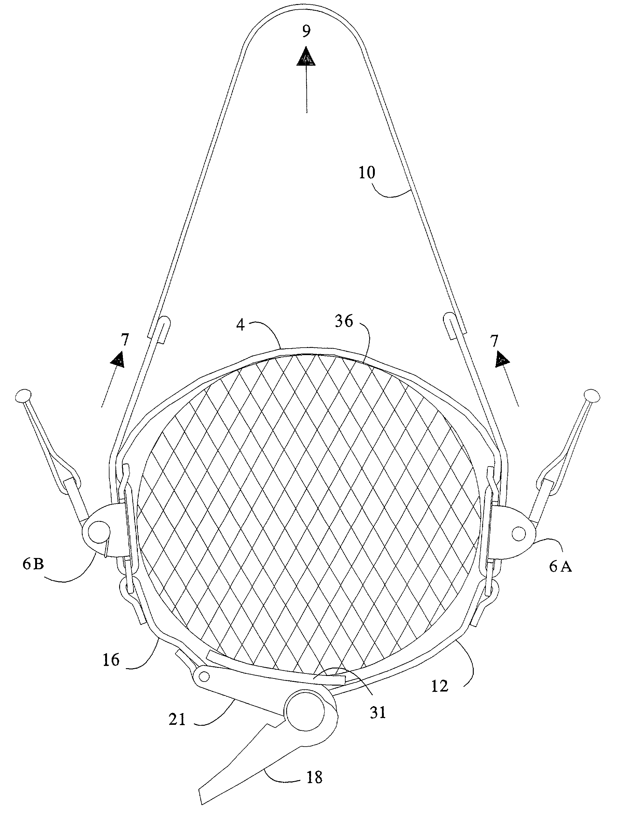
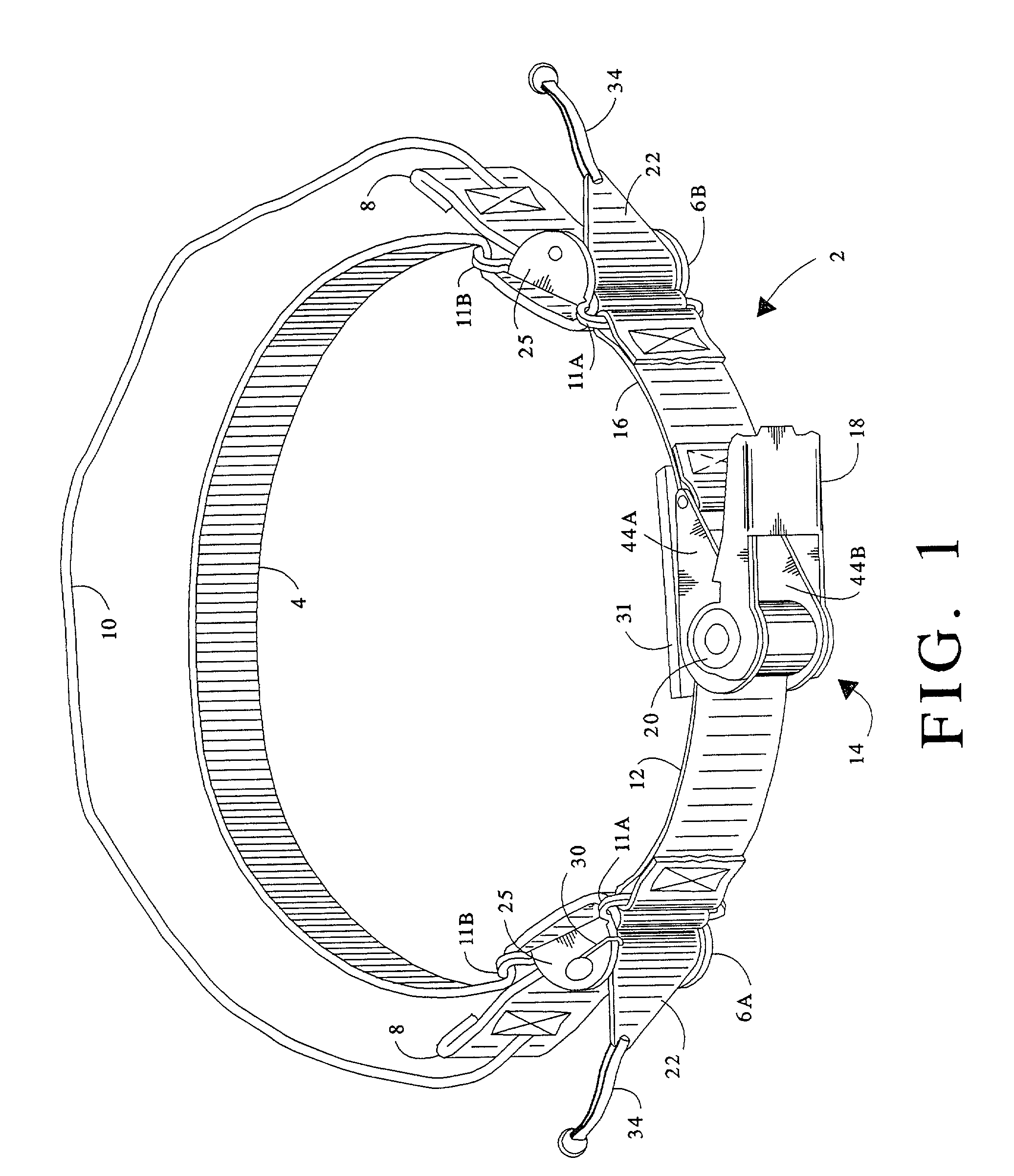
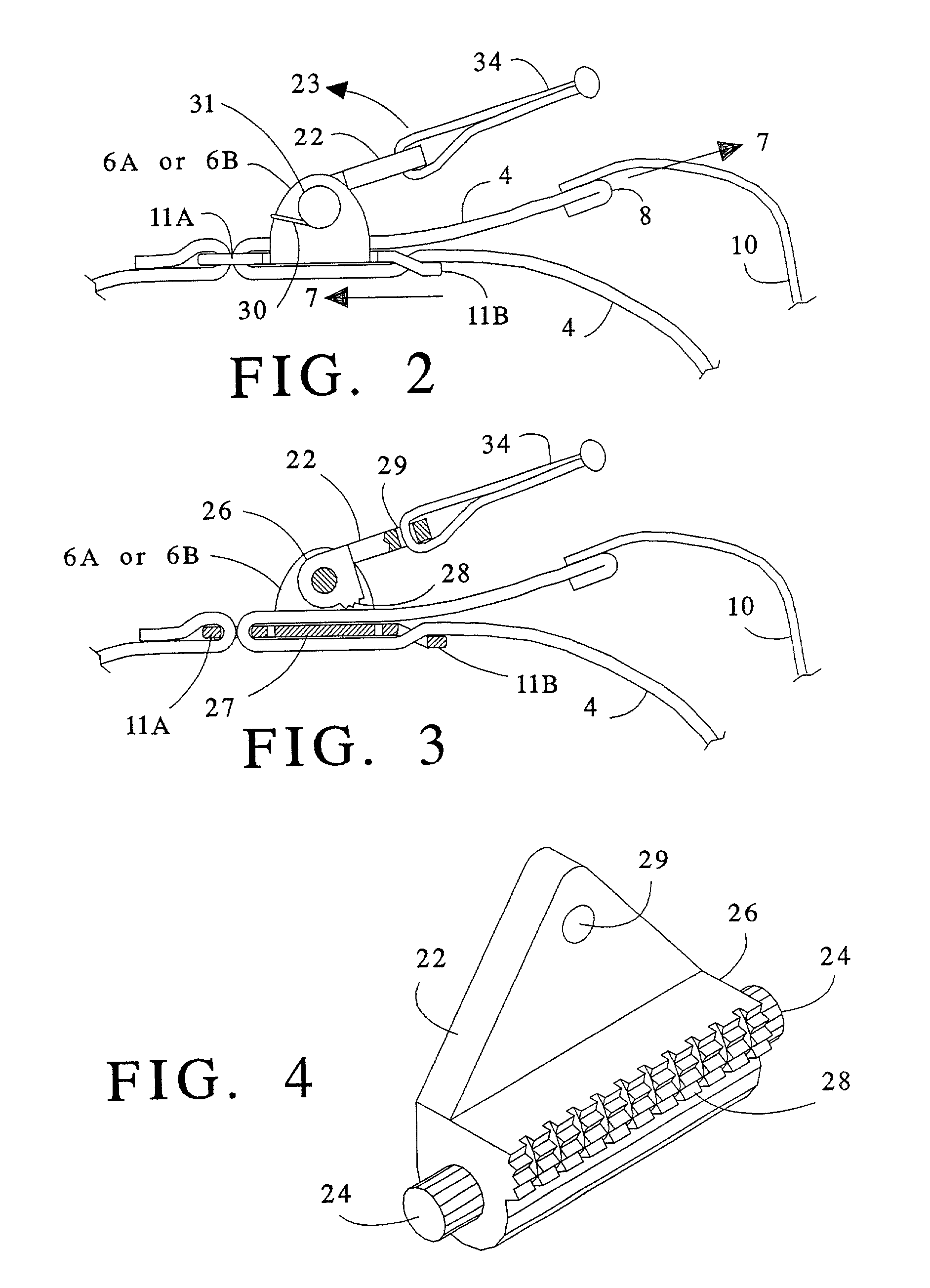
[0019]Referring to FIGS. 1 through 5, the tourniquet device of this invention as illustrated is generally designated 2. The invention has a first belt 4 having opposite ends 8 which loop back through respective “slip” buckles, 6A and 6B, which are so called because they each allow the belt 4 to easily slip through in one direction, indicated by arrow 7, but prevent movement of the belt through said each in the opposite direction. The first belt functions as one of two adjustable length segments of a tourniquet loop of this invention. A pull cord 10 extends between the first belt's opposite ends, each end of the pull cord being connected to a respective end 8 of the first belt 4. In operation, pulling the cord (in the general direction indicated by arrow 9 in FIG. 7) draws the end portions of the first belt further through respective slip buckles, in directions indicated by the arrows 7, and thereby shortens the segment of the first belt disposed between the slip buckles. Alternative...


PUM


Abstract

A first belt extends between and through two opposing slip buckles which allow the belt to be pulled freely through them but only in respective directions which shorten the belt segment between the buckles. Each slip buckle includes a release which when operated allows the belt to slip freely through said each buckle in either direction. A second belt is affixed at one end to one of the slip buckles, the other end being connected to a mechanism by which a user can spool the second belt to selectively shorten its free length. The spooling mechanism is coupled to the other slip buckle, preferably by means of a fixed length belt, to complete a tourniquet loop. Preferably the spooling mechanism includes a rachet mechanism operated by a lever in a pumping manner. Preferably the loop can be opened and closed.

Description

BACKGROUND OF THE INVENTION[0001]This invention relates in general to the field of tourniquets and more particularly to a tourniquet device which can be operated with just one hand.[0002]Tourniquets are well known for the purpose of temporarily restricting the flow of blood to a person's injured limb in order to prevent a serious loss of blood. If a person's arm is injured to the extent that significant blood is being lost, another person can generally fashion a tourniquet from available materials, such as a belt, rope, cord, or cloth, and apply it to the injured arm to restrict or stop the bleeding, allowing time to seek medical attention. However, when such an injury occurs where assistance is unavailable and the injured arm is incapacitated or severed, it is difficult if not impossible for the injured person to effectively apply a tourniquet to the injured arm, and depending on the rate of blood loss, the injured person may have only a very short time to stop the bleeding in orde...

Claims


Application Information

Patent Timeline
Patent Type & Authority Patents(United States)
IPC IPC(8): A61B17/12A61B17/132A61B17/00
CPCA61B17/1327A61B17/1322A61B2017/0042
Inventor AMBACH, ROBERT
Owner AMBACH ROBERT
Why Eureka
Try Eureka