Occlusive devices

a technology of occlusive devices and medical implants, applied in the field of intrasaccular medical devices, can solve the problems of thin walls and prone to rupturing of aneurysms, and achieve the effects of promoting endothelialization, facilitating thrombosis, and high surface area coverag

Active Publication Date: 2017-03-23
TYCO HEALTHCARE GRP LP
View PDF16 Cites 48 Cited by
  • Summary
  • Abstract
  • Description
  • Claims
  • Application Information

AI Technical Summary

Benefits of technology

[0007]Systems and procedures for treating aneurysms can include an implantable device that can be inserted into an aneurysm to facilitate a thrombotic, healing effect. The implantable device can have specific characteristics, including porosity, composition, material, shape, size, interconnectedness, inter-engagement, coating, etc. These characteristics can be selected in order to achieve a desired treatment or placement of the implantable device.
[0008]Implants or implantable devices for occluding a target area of a patient's vasculature, such as an aneurysm, can comprise a frame or frame component and one or more mesh components for mesh components that are coupled to the frame. The implantable device can be configured to provide an atraumatic, high surface area region that can promote endothelialization when the implantable device is implanted into a body lumen. The high surface area coverage can be created using a mesh component positioned along a given region of the frame. In some embodiments, a single mesh component can be coupled to the frame that has a generally constant porosity. However, the single mesh component can have a variable porosity. Further, multiple mesh components can be coupled to the frame that each have different porosities.
[0009]In some embodiments, the implantable device can have an average porosity that changes from a first end or region of the device to a second end or region of the device. Different regions of the device can define different porosities due to the presence of one or more mesh components in a given region or based on the porosity of the frame itself in a given region. Some embodiments therefore provide an implantable device that can have a first porosity in a distal region and a second porosity and a proximal region based on the presence of the mesh component in the proximal region of the device.
[0010]The subject technology is illustrated, for example, according to various aspects described below. Various examples of aspects of the subject technology are described as numbered embodiments (1, 2, 3, etc.) for convenience. These are provided as examples and do not limit the subject technology. It is noted that any of the dependent embodiments may be combined in any combination with each other or one or more other independent embodiments, to form an independent embodiment. The other embodiments can be presented in a similar manner. The following is a non-limiting summary of some embodiments presented herein:
[0011]Clause 1. An implant for occluding a target area of a patient's vasculature, comprising: a frame comprising a plurality of braided filaments that define a plurality of openings, the plurality of filaments and openings collectively defining a frame porosity, the frame comprising a distal region and a proximal region, the frame being expandable from a compressed configuration to an expanded configuration; and a mesh component coupled to the frame along at least the proximal region thereof, the mesh component comprising a plurality of filaments and a plurality of openings, the plurality of filaments and openings collectively defining a first porosity permitting blood flow therethrough, the first porosity being less than the frame porosity, such that blood flow into the implant is more restricted along the proximal region than along the distal region of the frame.

Problems solved by technology

As is well known, aneurysms have thin, weak walls that are prone to rupturing.
When the weakened wall of an aneurysm ruptures, it can result in death.

Method used


Image

  • Occlusive devices
  • Occlusive devices
  • Occlusive devices

Examples


Embodiment Construction

[0074]In the following detailed description, numerous specific details are set forth to provide a full understanding of the subject technology. It should be understood that the subject technology may be practiced without some of these specific details. In other instances, well-known structures and techniques have not been shown in detail so as not to obscure the subject technology.

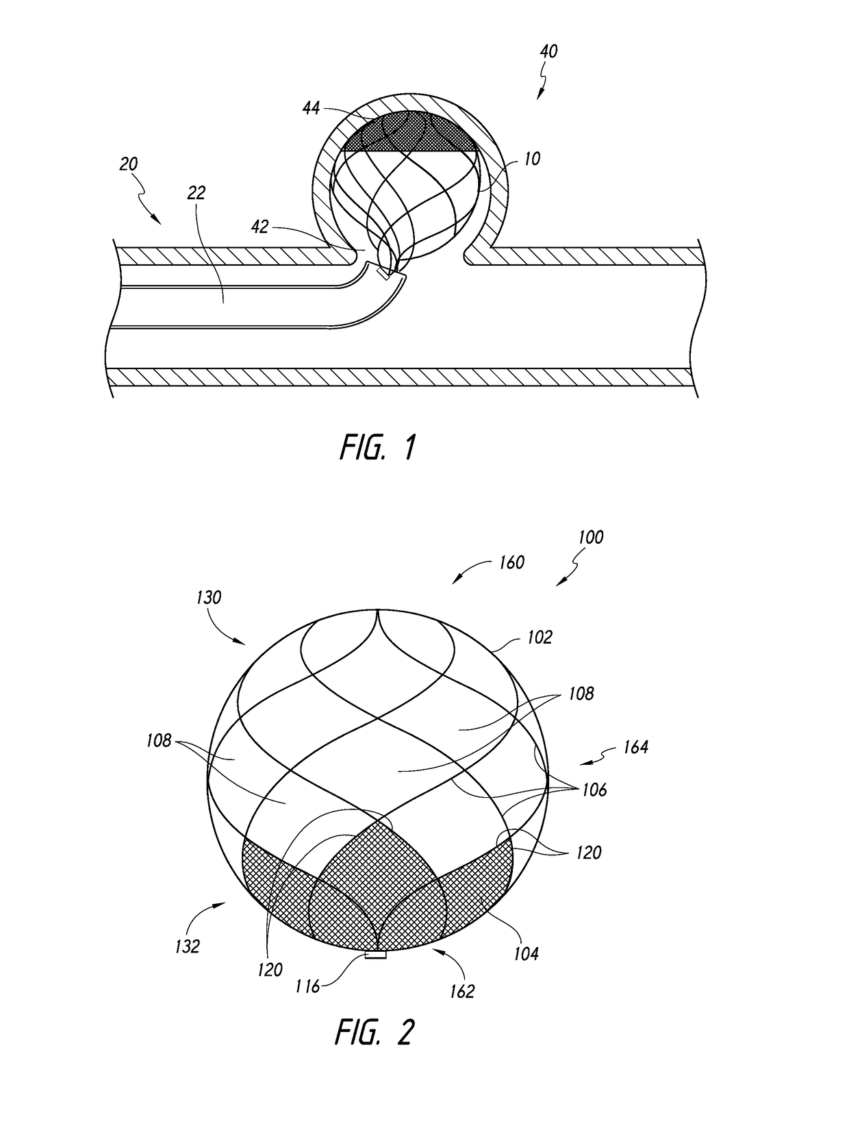
[0075]Referring now to the figures, FIG. 1 is a side cross-sectional view illustrating deployment of a device into an aneurysm, according to some embodiments. As shown, a device 10 can be advanced to a target aneurysm 40 using a device assembly 20. The device 10 can be advanced from a catheter 22 of the assembly 20 and through a neck 42 of the aneurysm 40 toward a fundus 44 of the aneurysm 40.

[0076]FIG. 2 illustrates an implantable device 100 that comprises a frame 102 and a mesh component 104. The mesh component 104 is coupled to filaments 106 that make up the frame 102. For example, the frame 102 can be ...


PUM


Abstract

An implant can include a frame and a mesh component coupled to the frame. The mesh component can define a first porosity, and the frame can define a frame porosity. The combined porosity of the mesh component and the frame can restrict blood flow into the implant.

Description

BACKGROUND[0001]Field of the Inventions[0002]The present disclosure generally relates to intrasaccular medical devices, and more particularly, to a medical implant having a frame and a mesh component for occluding a target area of a patient's vasculature.[0003]Description of the Related Art[0004]Walls of the vasculature, particularly arterial walls, may develop areas of pathological dilatation called aneurysms. As is well known, aneurysms have thin, weak walls that are prone to rupturing. Aneurysms can be the result of the vessel wall being weakened by disease, injury or a congenital abnormality. Aneurysms could be found in different parts of the body with the most common being abdominal aortic aneurysms (AAA) and brain or cerebral aneurysms. When the weakened wall of an aneurysm ruptures, it can result in death.[0005]Aneurysms are generally treated by excluding the weakened part of the vessel from the arterial circulation. For treating a cerebral aneurysm, such reinforcement is don...

Claims


Application Information

Patent Timeline
Patent Type & Authority Applications(United States)
IPC IPC(8): A61B17/12
CPCA61B17/12113A61B2017/00526A61B17/12031A61B17/12109A61B17/12118A61B17/12172A61B2017/00831A61B17/12177A61B17/12186A61B17/12168
Inventor RHEE, RICHARDBARDSLEY, EARL
Owner TYCO HEALTHCARE GRP LP
Why Eureka
Try Eureka