Air bag system mounting structure

a technology for mounting structures and air bags, applied in the direction of superstructure subunits, pedestrian/occupant safety arrangements, vehicle components, etc., can solve the problems of difficult to obtain a stable fixing strength, difficult to achieve processing time and costs disadvantageous factors, and deterioration of the aesthetic appearance of the instrument panel, etc., to achieve easy and secure fixation of the air bag modul

Inactive Publication Date: 2005-11-22
HONDA MOTOR CO LTD
View PDF12 Cites 9 Cited by
  • Summary
  • Abstract
  • Description
  • Claims
  • Application Information

AI Technical Summary

Benefits of technology

[0011]It is an object of the invention to provide an air bag system mounting structure to attain an easy and secure fixation of an air bag module to a lower surface of an instrument panel without deteriorating an aesthetic appearance of a surface of the instrument panel.

Problems solved by technology

In a case where the instrument panel is constructed as a single-layer instrument panel which does not have a foam layer, the fixing method uses the bolts which are exposed from the surface of the instrument panel, so that the fixing method has a problem that the aesthetic appearance of the instrument panel is deteriorated by the bolts.
In addition, processing time and costs become disadvantageous factors when the fixing method is used in which the bosses are heat clamped for fixing the air bag module to the instrument panel.
Furthermore, it is difficult to obtain a stable fixing strength due to change in processing conditions.
Further, there is caused a problem that a surface sink is generated in the surface of the instrument panel at positions corresponding to the positions of the bosses, whereby the aesthetic appearance of the instrument panel is deteriorated.

Method used


Image

  • Air bag system mounting structure
  • Air bag system mounting structure
  • Air bag system mounting structure

Examples


first embodiment

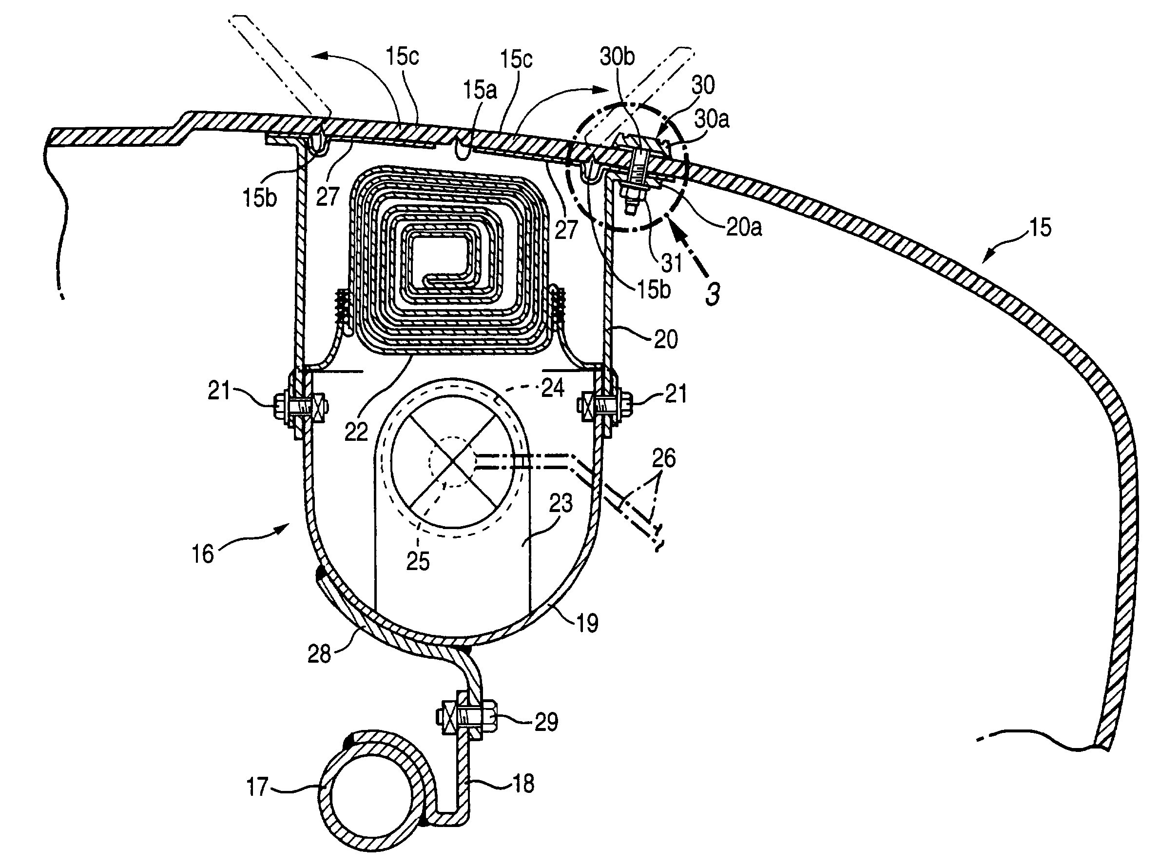
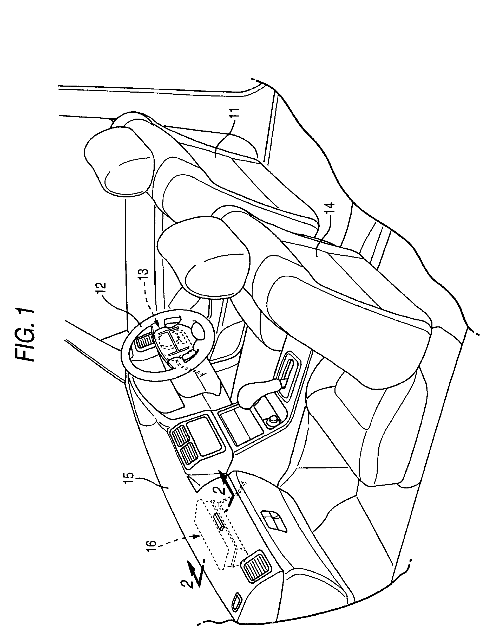
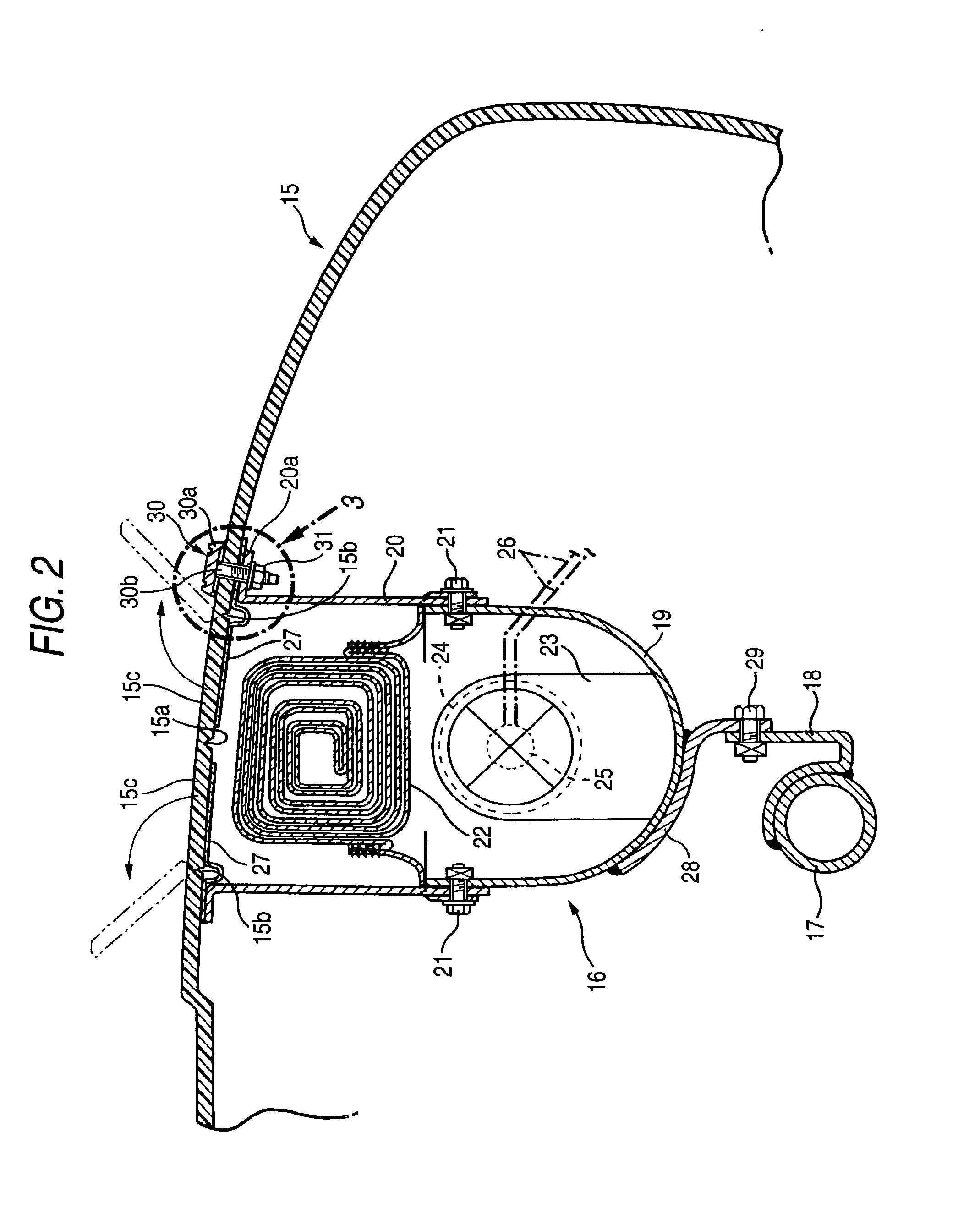
[0035]FIGS. 1 to 4 shows the invention. FIG. 1 is a perspective view of a front section of a passenger compartment of a vehicle. FIG. 2 is showing an enlarged cross sectional view taken along a line 2—2 in FIG. 1. FIG. 3 is showing an enlarged view of a portion denoted by reference numeral 3 in FIG. 2. FIG. 4 is an exploded perspective view of an emblem.

[0036]As shown in FIG. 1, an air bag module 13 for a driver is housed in the interior of a steering wheel facing a front side of a driver's seat of the vehicle, and an air bag module 16 for a front-seat passenger is housed in the interior of an instrument panel 15 facing a front side of a front passenger seat 14.

[0037]From FIGS. 2 to 4, a pillar-to-pillar pipe 17 is disposed in the interior of the instrument panel. The pillar-to-pillar pipe 17 connects to left and right front pillars.

[0038]A module supporting bracket 18 is welded to the pillar-to-pillar pipe 17.

[0039]The air bag module 16 for the front-seat passenger includes a lower...

second embodiment

[0053]Next, the invention will be described with reference to FIG. 5.

[0054]According to the second embodiment, the main body portion 30a of the emblem 30 is made from a synthetic resin. Two bolts 30b, 30b, whose head portions are embedded in a main body portion 30a of the emblem 30, protrude downwardly from a lower side thereof. According to the second embodiment, the production costs can be reduced by making the main body portion 30a of the emblem 30.from the synthetic resin.

third embodiment

[0055]Next, the invention will be described with reference to FIG. 6.

[0056]An emblem 30 according to the third embodiment has two nuts 30c, 30c which protrude from a reverse face of the main body portion 30a of the emblem 30. The nuts 30c, 30c pass, respectively, through an instrument panel 15, a hinge plate 27 and a mounting portion 20a of an upper retainer 20 and two bolts 32, 32 screwed and fastened in the nuts 30c, 30c, respectively. With this embodiment, too, the function and effectiveness similar to those provided by the second embodiment can be provided.

[0057]While the embodiments of the invention have thus been described in detail, various modifications in design may be made to the invention without departing from the spirit and scope of the invention.

[0058]For example, while the two bolts 30b, 30b or the two nuts 30c, 30c are provided on the emblem 30, the numbers of bolts and nuts can be modified as required. In addition, two or more emblems 30 may be used.

[0059]In additio...


PUM


Abstract

An air bag system for a front-seat passenger, includes a main body portion of an emblem is brought into contact with a surface of an instrument panel at a reverse face thereof, a bolt provided on the reverse face of the main body portion to protrude therefrom passes through the instrument panel and a mounting portion of an air bag module and a nut screwed on and fastened to the bolt so that the air bag module is fixed to the instrument panel easily and rigidly without using heat clamping which is less stable in quality. There is no risk that surface sinks are generated in the surface of the instrument panel to thereby deteriorate the aesthetic appearance thereof, since there is no need to provide bosses on a reverse face of the instrument panel for heat clamping.

Description

BACKGROUND OF THE INVENTION[0001]1. Field of the Invention[0002]The present invention relates to an air bag system mounting structure for fixing an instrument panel and a mounting portion of an air bag module.[0003]2. Description of the Related Art[0004]An air bag module for a front-seat passenger is housed in the interior of an instrument panel. For example, the air bag module is supported on a pillar-to-pillar pipe which connects to left and right front pillars.[0005]As a method for fixing to position a lower surface of the instrument panel and an upper surface of the air bag, JP-A-7-291078 discloses a method of fitting bosses protruded from a lower surface of an instrument panel of synthetic resin in mount holes, which are formed in a retainer of an air bag module, and then heat-clamping the bosses to fix the air bag module to the instrument panel.[0006]Incidentally, in a case where a foam layer is provided between a skin and a base material of an instrument panel for a luxury sp...

Claims


Application Information

Patent Timeline
Patent Type & Authority Patents(United States)
IPC IPC(8): B60R21/20B60R13/02B60R21/205B60R21/215B60R21/2165
CPCB60R21/2165B60R2021/21537B60R2021/21543
Inventor KOBAYASHI, TORUNAGATA, TAKASHIYAMADA, MAKOTOMORITA, YOSHIHIKO
Owner HONDA MOTOR CO LTD
Why Eureka
Try Eureka