Portable multimedia projection system

a multimedia projection and portable technology, applied in the field of multimedia projection systems, can solve the problems of large projectors, large projectors, and small tubes (perhaps 9-inch diagonals), and achieve the effects of low cost, large projector weight, and large projectors

Inactive Publication Date: 2005-11-22
JOHNSON RES & DEV INC
View PDF27 Cites 81 Cited by
  • Summary
  • Abstract
  • Description
  • Claims
  • Application Information

AI Technical Summary

Problems solved by technology

These tubes are small (perhaps 9-inch diagonal), expensive and extremely bright.
CRT devices do not have the fine resolution that LCD devices do, especially when projected.
One of the problems with conventional CRT projectors is that, with anywhere from one to three tubes and accompanying lenses and / or a filter wheel built in, the projectors can be quite heavy and large.
However, there is no real explanation of how an internal speaker, especially an amplified speaker or sound system, might be installed so as not to negatively impact upon the projection device.
However, what is absent in the Denmeade publication is a teaching for using such a projection system with an integral, amplified sound system so that vibration can be curtailed to avoid shaking or disturbing the projection.
Furthermore, the projection system in the Denmeade publication is lacking additional functionality such as wireless input / output (I / O) for receiving data from a network or communicating with wireless speakers as well as other I / O which might enhance the possible applications of such a projection system.
However, these systems have the inherently large stabilizing mass of the CRT type projectors used in these systems and the heavy cabinet of the TV itself such that the need for additional, separate integrated vibration stabilization of the projection component is less significant.

Method used


Image

  • Portable multimedia projection system
  • Portable multimedia projection system
  • Portable multimedia projection system

Examples


Embodiment Construction

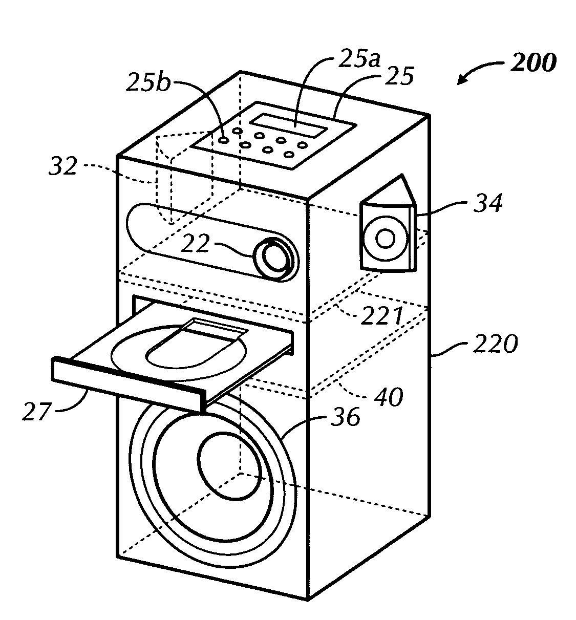
[0031]Certain terminology is used in the following description for convenience only and is not limiting. The words “right,” and “left,”“lower,” and “upper” designate directions in the drawings to which reference is made. The words “inwardly” and “outwardly” refer to directions toward and away from, respectively, the geometric center of the object discussed and designated parts thereof. The terminology includes the words above specifically mentioned, derivatives thereof and words of similar import. Additionally, the word “a” is used in the claims and in the corresponding portions of the Specification, means “at least one.”

[0032]“DVD” once was the abbreviation for Digital Video Disc and later became Digital Versatile Disc but now “DVD” is just DVD, and really is no longer an acronym that it once was. As used herein “DVD” is an optical disc format for storing video, audio and / or data. It should be noted that a DVD disc may contain any combination of DVD-Video, DVD-Audio, and / or DVD-ROM...


PUM

PropertyMeasurementUnit
aspect ratioaaaaaaaaaa
poweraaaaaaaaaa
elastic energyaaaaaaaaaa

Abstract

A portable multimedia projection system includes a portable housing, a media player disposed, a sound system, an image projection device, a controller and a vibration dampening device. The sound system has at least one internally-mounted speaker. The image projection device externally projects images. The controller is electrically coupled to the media player, the sound system and the image projection device. The controller directs audio signals from the media player to the sound system and directs video signals from the media player to the image projection device. The vibration dampening device is coupled between the housing and at least one of the media player, the at least one internally-mounted speaker and the image projection device.

Description

CROSS-REFERENCE TO RELATED APPLICATIONS[0001]This application claims the benefit of now abandoned U.S. Provisional Patent Application No. 60 / 512,673, filed Oct. 20, 2003, entitled “Portable Multimedia Projection System,” the disclosure of which is incorporated herein by reference.BACKGROUND OF THE INVENTION[0002]The present invention relates generally to a multimedia projector and, more particularly, to a portable multimedia projection system having a vibration dampening or suppression device.[0003]In the past projection systems have been based on high intensity cathode ray tube (CRT) technology. Like conventional TVs, CRT projectors have smaller CRT tubes built into them. These tubes are small (perhaps 9-inch diagonal), expensive and extremely bright. In a basic layout, there are typically one or more CRT tubes that form the images. A lens in front of the CRT magnifies the image and projects it onto the screen. CRT devices do not have the fine resolution that LCD devices do, especi...

Claims


Application Information

Patent Timeline
Patent Type & Authority Patents(United States)
IPC IPC(8): G03B31/00G03B21/30G03B21/14G03B21/00G11B17/04G11B31/00G11B33/02G11B33/08H04N5/64H04N5/74H04Q
CPCG03B29/00G11B17/056H04N9/3141G11B33/025G11B33/08G11B31/00
Inventor JOHNSON, LONNIE G.
Owner JOHNSON RES & DEV INC
Why Eureka
Try Eureka