
Emergency vehicle approach warning method and system

Inactive Publication Date: 2005-11-22
IBM CORP
View PDF17 Cites 16 Cited by
  • Summary
  • Abstract
  • Description
  • Claims
  • Application Information

AI Technical Summary

Benefits of technology

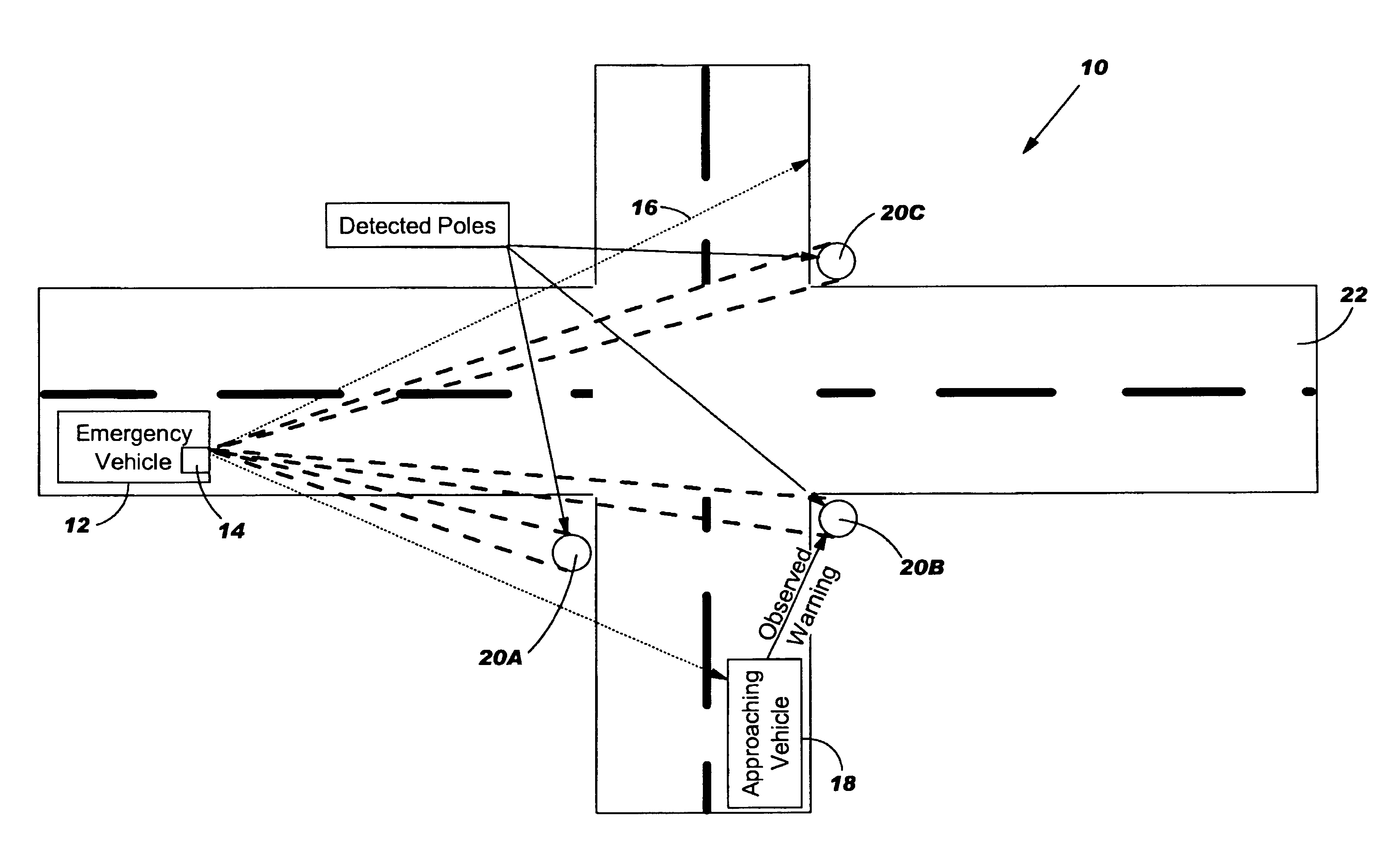
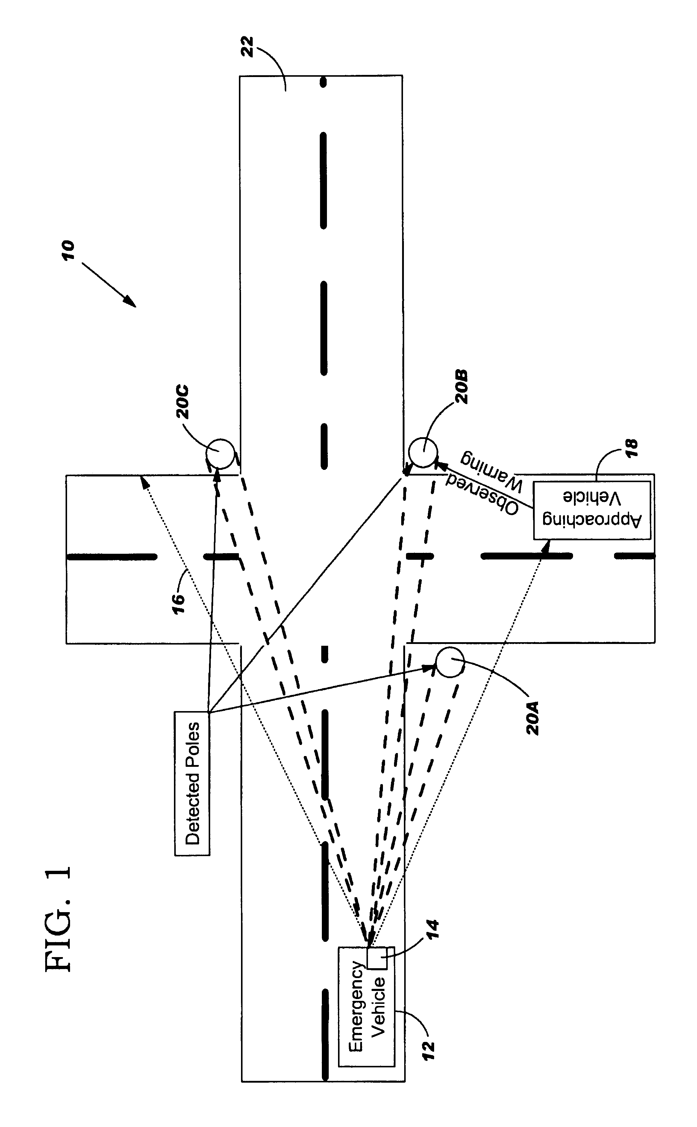
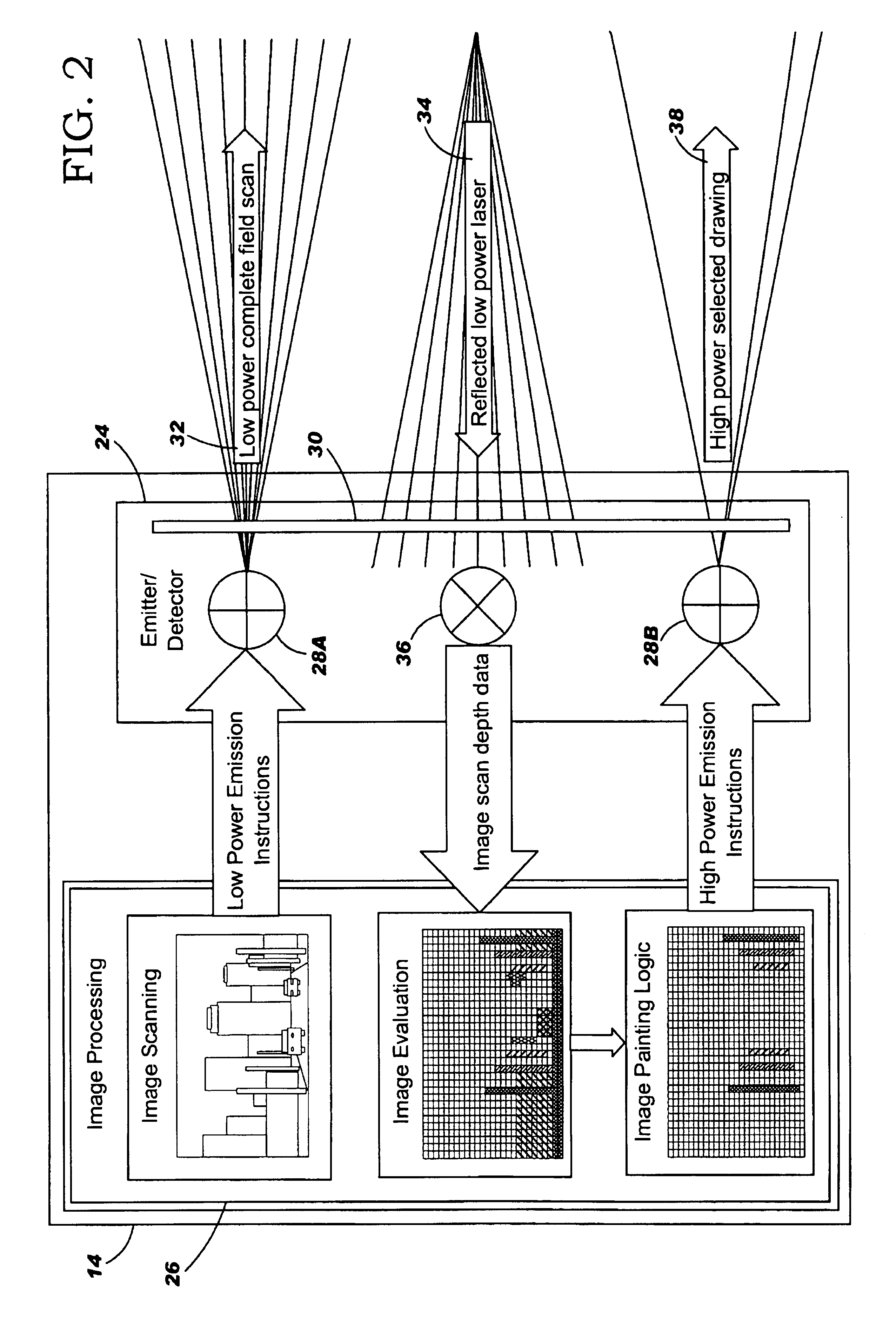
[0006]In general, the present invention provides an emergency vehicle approach warning method and system. Specifically, under the present invention, a warning unit having a light source (e.g., a laser) is mounted on an emergency vehicle. The light source first emits a low intensity light beam (e.g., an infrared light beam) to scan an area in front of the emergency vehicle. The scan is used to detect one or more objects having a height to width ratio exceeding a predetermined threshold. Specifically, the scan is used to detect one or more tall, narrow objects su

Problems solved by technology

Specifically, when responding to an emergency, an emergency vehicle must often traverse the streets in a potentially dangerous manner.
Although this could be necessary to properly respond to the emergency, it could create hazardous conditions for other motorists.
Part of the overall problem is the inability of the other motorists to accurately detect the direction from which an emergency vehicle is coming.
For example, although a motorist might hear sirens, he / she might not be able to determine the direction from which the sound is coming.
Sirens can also be inadequate because they are often not heard until the emergency vehicle is imminent.
In addition, a siren may not even be heard by another motorist due to various distractions within his / her vehicles (e.g., a radio being played too loudly).
As such, many sirens fail to provide ample warning time.
Unfortunately, this system not only requires a transmitter to be positioned on the emergency vehicles, but receivers to be positioned on each traffic signal as well.
As such, the implementation and maintenance of such a system can be extremely costly.
In addition, with both of these systems, there is often a latency involved in changing the traffic signal, or warning the approaching vehicles.
Such a latency could be the cause for accidents and injury.

Method used


Image

  • Emergency vehicle approach warning method and system
  • Emergency vehicle approach warning method and system
  • Emergency vehicle approach warning method and system

Examples


Embodiment Construction

[0020]As indicated above, the present invention provides an emergency vehicle approach warning method and system. Specifically, under the present invention, a warning unit having a light source (e.g., a laser) is mounted on an emergency vehicle. The light source first emits a low intensity light beam (e.g., an infrared light beam) to scan an area in front of the emergency vehicle. The scan is used to detect one or more objects having a height to width ratio exceeding a predetermined threshold. Specifically, the scan is used to detect one or more tall, narrow objects such as poles, sign posts, etc., while ignoring other objects such as people, animals, buildings, etc. Once any applicable objects are detected, a second, higher intensity light beam is emitted to illuminate the detected objects with a predetermined indicia. The predetermined indicia can be observed by other motorists and indicates to them a direction of origin of the emergency vehicle. Typically, the scan, detect and il...


PUM


Abstract

Under the present invention, a warning unit having a light source (e.g., a laser) is mounted on an emergency vehicle. The light source first emits a low intensity light beam (e.g., an infrared light beam) to scan an area in front of the emergency vehicle. The scan is used to detect one or more objects having a height to width ratio exceeding a predetermined threshold. Specifically, the scan is used to detect one or more tall, narrow objects such as poles, sign posts, etc., while ignoring other objects such as people, animals, etc. Once any applicable objects are detected, a second, higher intensity light beam is emitted to illuminate the detected objects with a predetermined indicia. The predetermined indicia can be observed by other motorists and indicates to them a direction of origin of the emergency vehicle.

Description

FIELD OF THE INVENTION[0001]In general, the present invention provides an emergency vehicle approach warning method and system. Specifically, under the present invention, light imaging technology is utilized to detect and illuminate certain objects along a roadway to warn motorists of an approaching emergency vehicle.BACKGROUND OF THE INVENTION[0002]As the number of vehicles on the road increases, roadway traffic is becoming a growing concern. This is especially the case in urban areas where the quantity of vehicles on the road often approaches or exceeds capacity. One particular area of concern involves emergency vehicles. Specifically, when responding to an emergency, an emergency vehicle must often traverse the streets in a potentially dangerous manner. This could involve exceeding local speed limits, passing other vehicles, and crossing intersections against the traffic signals. Although this could be necessary to properly respond to the emergency, it could create hazardous cond...

Claims


Application Information

Patent Timeline
IPC IPC(8): G08G1/0962G08G1/0965
CPCG08G1/0965
Inventor CARROLL, DENNIS J.
Owner IBM CORP
Learn More